 Kawasaki Z400 - Service manual > Vehicle-down Sensor (Service Code 31) (DTC C0064)
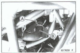
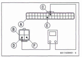
This sensor has a weight [A] with two magnets inside, and sends a signal to the ECU. But when the motorcycle banks 60 ~ 70° or more to either side (in fact falls down), the weight turns and the signal changes. The ECU senses this change, and stops the fuel pump relay, the fuel injectors and the ignition system.
Hall IC [B]
When the motorcycle is down, the ignition switch is left on.
If the starter button is pushed, the electric starter turns but the engine does not start. To start the engine again, raise the motorcycle, turn the ignition switch off, and then turn it on.
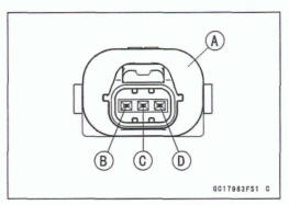
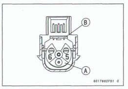
Vehicle-down Sensor [A]
Ground Terminal [B]: BR/BK
Output Terminal [C]: Y/G
Power Source Terminal [D]: G
Vehicle-down Sensor Removal
- Remove: Upper Fairing (see Upper Fairing Removal in the Frame chapter)
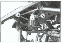
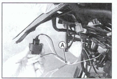
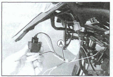
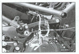
- Disconnect the vehicle-down sensor connector [A].
- Pull up the vehicle-down sensor [B] with rubber protector to dear the projection [C].
Vehicle-down Sensor Installation
- Installation is the reverse of removal.
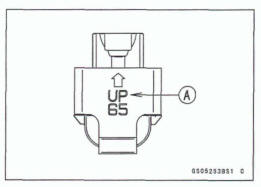
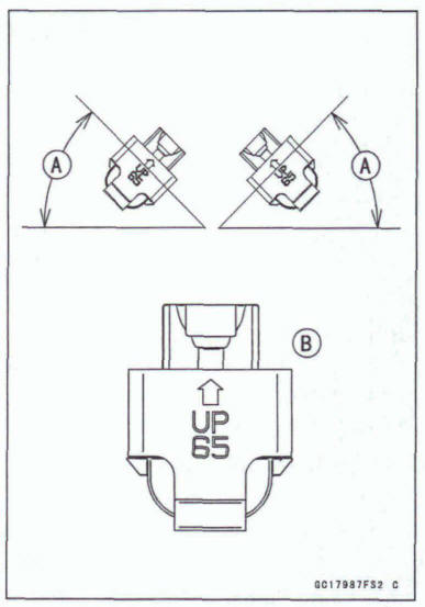
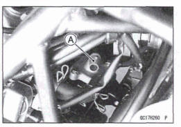
- The UP mark [A] of the sensor should face upward.
Warning
Incorrect installation of the vehicle-down sensor could cause sudden loss of engine power. The rider could lose balance during certain riding situations for an accident resulting in injury or death.
Ensure that the vehicle-down sensor is held in place by the sensor bracket.
- Install the removed parts (see appropriate chapters).
Vehicle-down Sensor (Service Code 31) (DTC C0064)
Note
Be sure the battery is fully charged.
- Turn the ignition switch off.
- Remove: Upper Fairing (see Upper Fairing Removal in the Frame chapter)
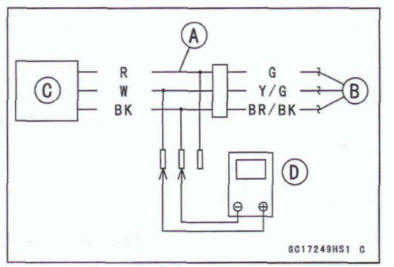
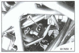
- Disconnect the vehicle-down sensor connector and connect the measuring adapter [A] between these connectors as shown.
Main Harness [B]
Vehicle-down Sensor [C]
Special Tool- Measuring Adapter: 57001 -1 700
- Connect a digital meter [D] to the measuring adapter leads.
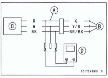
Vehicle-down Sensor Input Voltage Connections to Adapter
Digital Meter (+)→ R (sensor G) lead
Digital Meter (-) → BK (sensor BR/BK) lead
- Measure the input voltage with the engine stopped and with the connector joined.
- Turn the ignition switch on.
Input Voltage Standard: DC 4.75 - 5.25 V
- Turn the ignition switch off
*If the reading is within the standard, check the output voltage (see Vehicle-down Sensor Output Voltage Inspection).
*If the reading is out of the standard, remove the ECU and check the wiring for continuity between main harness connectors.
Disconnect the ECU and sensor connectors
Wiring Continuity Inspection
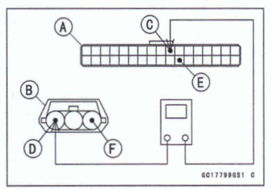
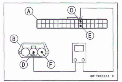
ECU Connector [A] ←→
Vehicle-down Sensor Connector [B]
ECU Terminal 10 [C] ←→ Sensor Terminal [D]
ECU Terminal 28 [E] ←→ Sensor Terminal [F]
If the wiring is good, check the ECU for its ground and power supply (see ECU Power Supply Inspection).
If the ground and power supply are good, replace the ECU (see ECU Removal/Installation).
Vehicle-down Sensor Output Voltage Inspection
- Remove the vehicle-down sensor (see Vehicle-down Sensor Removal).
- Connect the measuring adapter [A] to the vehicle-down sensor connectors as shown.
Main Harness [B] Vehicle-down Sensor [C]
Swat Tool- Measuring Adapter: 57001-1700
- Connect a digital meter [D] to the measuring adapter leads.
Vehicle-down sensor Output Voltage
Connections to Adapter: .
Digital Meter (+) → W (sensor Y/G) had
Digital Meter (-) → BK (sensor BR/BK) had
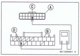
Hold the sensor vertically.
Measure the output voltage with the engine stopped and with the connector joined.
Turn the ignition switch on.
Tilt the sensor 60 ~ 70º or more [A] right or left, then hold the sensor almost vertical with the arrow mark pointed up [B], and measure the output voltage.
Output Voltage
Standard:
With sensor tilted 60 ~ 70º or more right or left: DC 0.65 ~ 1.35 V With sensor arrow mark pointed up: DC 3.55 ~ 4.45 V
- Turn the ignition switch off.
If the reading is out of the standard, replace the sensor (see Vehicle-down Sensor Removal/Installation).
If the reading is within the standard, remove the ECU and check the wiring for continuity between main harness connectors.
Disconnect the ECU and sensor connectors.
Wring Continuity Inspection
ECU Connector [A] ←→
Vehicle-down Sensor Connector [B] ECU Terminal 11 [C] ←→ Sensor Terminal [D] ECU Terminal 28 [E] ←→ Sensor Terminal [F]
If the wiring is good, check the ECU for its ground and power supply (see ECU Power Supply Inspection).
If the ground and power supply are good, replace the ECU (see ECU Removal/Installation).
Vehicle-down Sensor Circuit
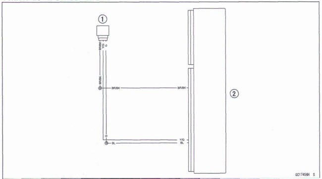
- Vehicle-down Sensor
- ECU
Oxygen Sensor - not activated (Service Code 33) (DTC P0130, P0132)
Oxygen Sensor Removal/Installation
- Refer to the Oxygen Sensor Removal/Installation in the Electrical System chapter
Oxygen Sensor Inspection
- Turn the ignition switch off.
- Remove the right middle fairing (see Middle Fairing Removal in the Frame chapter).
- Disconnect the oxygen sensor lead connector and connect the oxygen sensor measuring adapter [A] between these connectors
Special Tool - Oxygen Sensor Measuring Adapter: 57001 -1 682
- Connect a digital meter to the measuring adapter leads.
Oxygen Sensor Output Voltage
Connections to Adapter:
Digital Meter (+) → BL (sensor BL) lead
Digital Meter (-) → BR (sensor W) lead
- Slide the damp [A].
- Disconnect the air switching valve hose [B].
Install the suitable plug [A] on the fitting of the air suction valve cover, and shut off the secondary air.
- Warm up the engine thoroughly until the radiator fan starts.
- Measure the output voltage with the connector joined.
Output Voltage (with Plug, Rich) Standard: DC 0.5 V or more
Turn the ignition switch off.
Remove the plug from the fitting [A].
Start the engine, and let it idle.
Measure the output voltage with the connector joined.
Output Voltage (without Plug, Lean) Standard: DC 0.2 V or less
- Turn the ignition switch off.
If the reading is out of the standard (with plug: DC 0.5 V or more, without plug: DC 0.2 V or less), remove the ECU and check the wiring for continuity between main harness connectors.
Disconnect the ECU and sensor connectors.
Wiring Continuity Inspection
ECU Connector [A] ←→
Oxygen Sensor Connector [B]
ECU Terminal 9 [C] ←→ Sensor Terminal [D]
ECU Terminal 25 [E] ←→ Sensor Terminal [F]
If the wiring is good, replace the sensor (see Oxygen Sensor Removal/Installation in the Electrical System chapter).
*If the reading is within the standard (with plug: DC 0.5 V or more, without plug: DC 0.2 V or less), check the ECU for its ground and power supply (see ECU Power Supply Inspection).
*If the ground and power supply are good, replace the ECU (see ECU Removal/Installation).
Oxygen Sensor Circuit
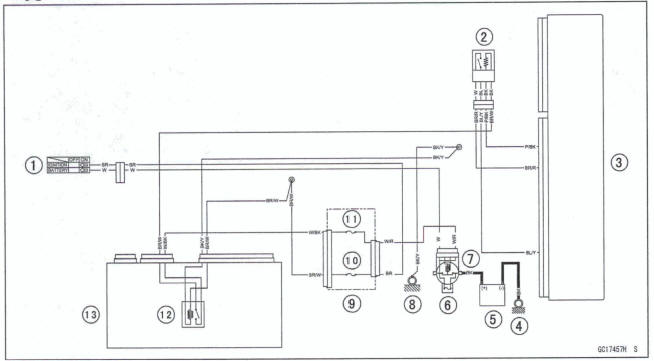
- Ignition Switch
- Oxygen Sensor
- ECU
- Engine Ground
- Battery
- Main Fuse 30 A
- Starter Relay
- Frame Ground (2)
- Fuse Box (1)
- Ignition Fuse 10 A
- ECU Fuse 15 A
- ECU Main Relay
- Relay Box
ECU Communication Error (Service Code 39)
ECU Communication Line Inspection
- When the data is not sent from the ECU to the meter unit for more than about 10 seconds, the service code 39 is displayed.
- The service code 39 is detected with meter unit.
- Remove the ECU and meter unit, check the wiring for continuity between main harness connectors
Disconnect the ECU and meter unit connectors.
Wiring Continuity Inspection
ECU Connector [A]←→ Meter Unit Connector [B]
ECU Terminal 48 [C] ←→ Meter Terminal [D]
If the wiring is good, check the meter unit (see Meter Unit Inspection in the Electrical System chapter).
If the meter unit is normal, replace the ECU (see ECU Removal/Installation).
ECU Communication Line Circuit
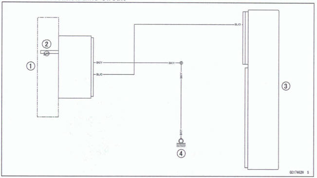
- Meter Unit
- Yellow Engine Warning Indicator Light (LED)
- ECU
- Frame Ground (4)
See also:
 Kawasaki Z400 - Service manual > Water Temperature Sensor (Service Code 14) (DTC PO115, PO 117)
Water Temperature Sensor Removal/Installation
Kawasaki Z400 - Service manual > Fuel Injectors (Service Code 41, 42) (DTC P0201, P0202)
Inspect the eligible fuel injector according to the following service code or DTC. Service Code 41/DTC PO201→ Fuel Injector #1
 Benelli Imperiale 400
 BMW F900XR
 Honda CB500X
 KTM 390 Adventure
 Triumph Street Triple S
 Yamaha MT-03
 Kawasaki Z400
 Triumph Street Triple S
 Yamaha MT-03