 Kawasaki Z400 - Service manual > Fuel Injectors (Service Code 41, 42) (DTC P0201, P0202)
Inspect the eligible fuel injector according to the following service code or DTC.
Service Code 41/DTC PO201→ Fuel Injector #1
Service Code 42/DTC PO202 → Fuel Injector #2
Fuel Injector Removal/Installation
- Refer to the Throttle Body Assy Disassembly/Assembly.
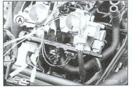
Fuel Injector Audible Inspection
NOTE
Be sum the battery is fully charged
- Remove the right side cover (see Side Cover Removal in the Frame chapter).
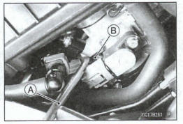
- Start the engine, and let it idle.
- Apply the flat tip screwdriver [A] to the fuel injector [B].
Put the grip end onto your ear, and listen whether the fuel injector is clicking or not.
A sound scope can also be used.
The click interval becomes shorter as the engine speed rises.
- Do the same for the other fuel injectors.
If all the fuel injectors click at a regular intervals, the fuel injectors are normal
- Turn the ignition switch off.
If any fuel injector does not click, check the fuel injector resistance (see Fuel Injector Resistance Inspection).
Fuel Injector Resistance Inspection
- Remove the air cleaner housing (see Air Cleaner Housing Removal).
- Disconnect the fuel injector connector.
- Connect a digital meter to the terminals [A] in each fuel injector.
- Measure the fuel injector resistance.
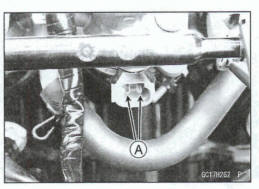
Fuel Injector Resistance
Standard: About 12.0  @20ºC (68ºF)
*If the reading is out of the standard, replace the fuel injector (see Throttle Body Assy Disassembly/Assembly).
*If the reading is within the standard, check the power source voltage (see Fuel Injector Power Source Voltage Inspection).
Fuel Injector Power Source Voltage Inspection
NOTE
Be sure the battery is fully charged
Turn the ignition switch off.
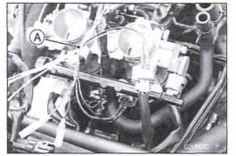
Remove the air cleaner housing (see Air Cleaning Housing Removal).
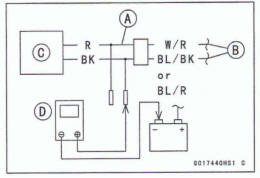
Disconnect the fuel injector connector and connect the measuring adapter [A] between these connectors as shown.
Main Harness [B]
Fuel Injector [C]
Special Tool - Measuring Adapter 57001 -1700
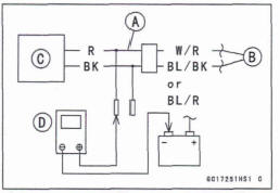
Connect a digital meter [D] to the measuring adapter lead.
Fuel Injector Power Source Voltage Connections to Adapter:
For Fuel Injector #1, #2
Digital Meter (+) → R (injector W/R) lead
Digital Meter (-) → Battery (-) Terminal
- Measure the power source voltage with the engine stopped and with the connector joined.
- Turn the engine stop switch to run position.
- Turn the ignition switch on.
Power Source Voltage Standard: Battery Voltage for 3 seconds, and then 0 V
- Turn the ignition switch off.
*If the reading stays on battery voltage and never shows 0 V, check the fuel pump relay (see Relay Circuit Inspection in the Electrical System chapter).
*If the fuel pump relay is normal, check the ECU for its ground and power supply (see ECU Power Supply Inspection).
+If the ground and power supply are good, replace the ECU (see ECU Removal/Installation).
*If there is still no battery voltage, check the fuel pump relay (see Relay Circuit Inspection in the Electrical System chapter).
*If the fuel pump relay is normal, check the power source wiring (see Fuel Injector Circuit).
*If the wiring is good, check the ECU for its ground and power supply (see ECU Power Supply Inspection).
*If the ground and power supply are good, replace the ECU (see ECU Removal/Installation).
*If the reading is in specification, check the output voltage (see Fuel Injector Output Voltage Inspection).
Fuel Injector Output Voltage Inspection
NOTE
Be sure the battery is fully charged.
- Turn the ignition switch off.
- Remove: Air Cleaner Housing (see Air Cleaner Housing Removal)
- Disconnect the fuel injector connector and connect the measuring adapter [A] between these connectors as shown.
Main Harness [B]
Fuel Injector #1 [C]
Special Tool - Measuring Adapter: 570011700
Connect a digital meter [D] to the measuring adapter leads.
Fuel Injector Output Voltage
Connections to Adapter:
For Fuel Injector #1
Digital Meter (+) → BK (injector BL/BK)
Digital Meter (-) → Battery (-) Terminal
For Fuel Injector #2
Digital Meter (+) → BK (Injector BUR)
Digital Meter (-) → Battery (-) Terminal
- Measure the output voltage with the engine stopped and with the connector joined.
- Turn the engine stop switch to run position.
- Turn the ignition switch on.
Output Voltage
Standard: Battery Voltage for 3 seconds, and then 0 V
- Turn the ignition switch off.
If the reading is in specification, check the ECU for its ground and power supply (see ECU Power Supply Inspection).
If the ground and power supply are good, replace the ECU (see ECU Removal/Installation).
If the reading is out of the specification, remove the ECU and check the wiring far continuity between main harness connectors.
Disconnect the ECU and injector connector.
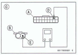
Wiring Continuity Inspection
ECU Connector [A] ←→ Fuel Injector Connector [B]
For Fuel Injector #1 [C] ECU Terminal 42 [D] ←→ Fuel Injector Terminal [E]
For Fuel Injector #2
ECU Terminal 41 ←→ Fuel Injector Terminal
+If the wiring is good, check the ECU for its ground and power supply (see ECU Power Supply Inspection).
*If the ground and power supply are good, replace the ECU (see ECU Removal/Installation).
Fuel Injector Fuel Line Inspection
- Remove: Air Cleaner Housing (see Air Cleaner Housing Removal) Fuel Hose (see Fuel Hose Replacement in the Periodic Maintenance chapter
Be sure to place a piece of cloth around the fuel outlet pipe of the fuel pump and the delivery pipe of the throttle body assy.
WARNING
Fuel is flammable and explosive under certain conditions and can cause severe burns. Be prepared for fuel spillage; any spilled fuel must be completely wiped up immediately. When the fuel hose Is disconnected, fuel spills out from the hose and the pip because of residual pressure. Cover the hose connection with a piece of clean cloth to prevent fuel spillage.
Check the fuel injector fuel line for leakage as follows.
Connect a commercially available vacuum/pressure pump [A] to the nipple of the delivery pipe [B] with the fuel hose [C] (both ends with the damps [D]) as shown.
Up Side View [E]
Apply soap and water solution to the areas [F] as shown.
Watching the pressure gauge, squeeze the pump lever [G], and build up the pressure until the pressure reaches the maximum pressure.
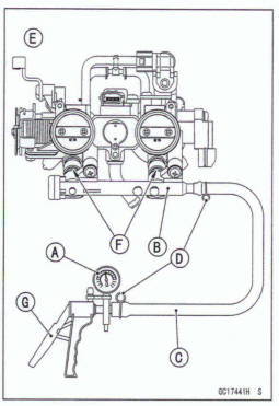
Injector Fuel Line Maximum Pressure Standard: 300 kPa (3.06 kgf/cm2, 43 psi)
Notice
During pressure testing, do not exceed the maxi- mum pressure for which the system is designed.
Watch the gauge for at least 6 seconds.
If the pressure holds steady, the fuel line is good.
If the pressure drops at once or If bubbles are found in the area, the fuel line is leaking. Replace the delivery pipe, fuel injectors and dated parts (see Throttle Body Assy Disassembly/Assembly).
Repeat the leak test, and check the fuel line for no leakage.
- Install: Fuel Hose (see Fuel Hose Replacement in the Periodic Maintenance chapter) Air Cleaner Housing (see Air Cleaner Housing Installation)
- Start the engine and check for fuel leakage
Fuel Injector Circuit
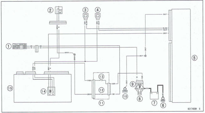
- Ignition Switch
- Engine Stop Switch
- Fuel Injector #1
- Fuel injector #2
- ECU
- Engine Ground
- Battery
- Main Fuse 30 A
- Starter Relay
- Frame Ground (2)
- Fuse Box (1 )
- Ignition Fuse 10 A
- ECU Fuse 15 A
- Fuel Pump Relay
- Relay Box
See also:
 Kawasaki Z400 - Service manual > Vehicle-down Sensor (Service Code 31) (DTC C0064)
This sensor has a weight [A] with two magnets inside, and sends a signal to the ECU. But when the motorcycle banks 60 ~ 70° or more to either side (in fact falls down), the weight turns and the signal changes. The ECU senses this change, and stops the fuel pump relay, the fuel injectors and the ignition system.
Kawasaki Z400 - Service manual > Stick Coils #1, #2 (Service Code 51, 52) (DTC P0351, P0352)
Inspect the eligible stick coil according to the following service code or DTC. Service Code 51/DTC PO351→ Stick Coil #1 Service Code 52/DTC PO352 →P Stick Coil #2
 Benelli Imperiale 400
 BMW F900XR
 Honda CB500X
 KTM 390 Adventure
 Triumph Street Triple S
 Yamaha MT-03
 Kawasaki Z400
 Triumph Street Triple S
 Yamaha MT-03