 Kawasaki Z400 - Service manual > Water Temperature Sensor (Service Code 14) (DTC PO115, PO 117)
Water Temperature Sensor Removal/Installation
Notice
Never drop the water temperature sensor especially on a hard surface. Such a shock to the sensor can damage it.
- Drain the coolant (see Coolant Change in the Periodic Maintenance chapter).
- Remove:
Left Middle Fairing
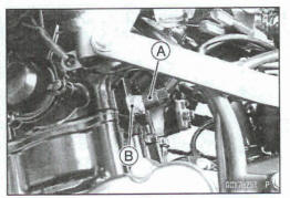
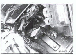
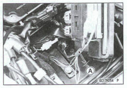
- Disconnect: Water Temperature Sensor Connector [A]
- Remove: Water Temperature Sensor [B] with O-ring
- Replace the O-ring with a new one.
- Tighten
Torque -Water Temperature Sensor: 12 N*m (1.2 kgf*m, 106 in*lb)
- Fill the engine with coolant and bleed the air from the cooling system (see Coolant Change in the Periodic Maintenance chapter).
Water Temperature Sensor Output Voltage Inspection
NOTE
Be sure the battery is fully charged
- Turn the ignition witch off.
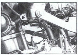
- Disconnect the water temperature sensor connector (see Water Temperature sensor Removal/Installation).
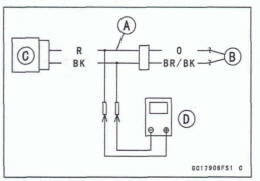
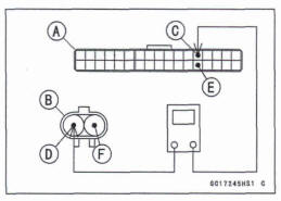
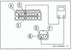
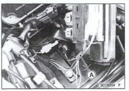
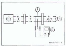
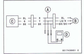
- Connect the measuring adapter [A] between these connectors as shown.
Main Harness [B] Water Temperature Sensor [C]
Special Tool - Measuring Adapter 57001-1700
Connect a digital meter [D] to the measuring adapter leads.
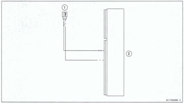
Water Temperature Sensor Output Voltage
Connections to Adapter:
Digital Meter (+)→R (sensor 0) lead
Digital Meter (-)→ BK (sensor BR/BK) lead
- Measure the output voltage with the engine stopped and with the connector joined.
- Turn the ignition switch on.
Output Voltage Standard: About DC 2.80 ῀ 2.97 V @20ºC (68ºF)
NOTE
The output voltage changes according to the coolant temperature in the engine.
- Turn the ignition switch off.
If the reading is within the standard, check the ECU for its ground and power supply (see ECU Power Supply Inspection).
If the ground and power supply are good, replace the ECU (see ECU RemovaVln6tallation).
If the reading is out of the standard, remove the ECU and check the wiring for continuity between main harness connectors.
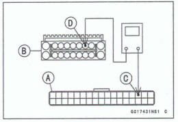
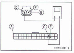
- Disconnect the ECU and sensor connectors
Wiring Continuity Inspection
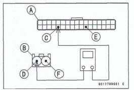
ECU Connector [A] ←→
Water Temperature Sensor Connector [B]
ECU Terminal 22 [C] ←→Sensor Terminal [D]
ECU Terminal 28 [E] ←→Sensor Terminal [F]
If the wiring is good, check the water temperature sensor resistance (see Water Temperature Sensor Resistance Inspection).
Water Temperature, Sensor Resistance Inspection
- Refer to the Water Temperature Sensor Inspection in the Electrical System chapter
If the reading Is within the standard, but the problem still exists, replace the ECU (see ECU Removal/Installation)
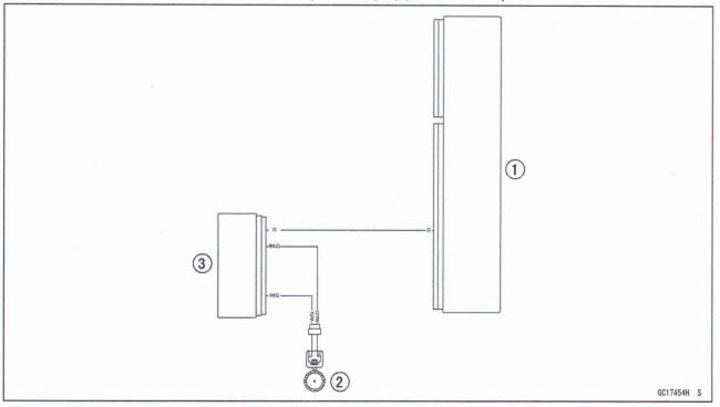
Water Temperature Sensor Circuit
- Water Temperature Sensor
- ECU
Crankshaft Sensor (Service Code 21) (DTC P0335)
The crankshaft sensor has no power source, and when the engine stops, the crankshaft sensor generates no signals.
Crankshaft Sensor Removal/Installation
Refer to the Crankshaft Sensor Removal/Installation in the Electrical System chapter.
Crankshaft Sensor Resistance inspection
- Refer to the Crankshaft Sensor Inspection in the Electrical System chapter
If the reading is within the standard, check the peak voltage (see Crankshaft Sensor Peak Voltage Inspection).
Crankshaft Sensor Peak Voltage Inspection
- Refer to the Crankshaft Sensor Peak Voltage Inspection in the Electrical System chapter.
If the reading is within the standard, remove the ECU and check the wiring for continuity between main harness connectors.
- Disconnect the ECU and sensor connectors
Wiring Continuity Inspection
ECU Connector [A] ←→
Crankshaft Sensor Connector [B]
ECU Terminal 13 [C] ←→ Sensor Terminal [D]
ECU Terminal 30 (E] ←→ Sensor Terminal [F]
If the wiring is good, check the ECU for its ground and power supply (see ECU Power Supply Inspection).
If the ground and power supply are good, replace the ECU (see ECU Removal/Installation).
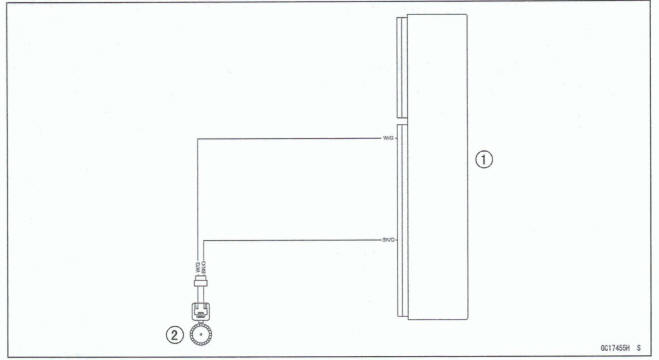
Crankshaft Sensor Circuit
- Crankshaft Sensor
- ECU
Rear Wheel Rotation Sensor (Service Code 24) (DTC P2158)
Rear Wheel Rotation Sensor Signal Inspection
- The rear wheel rotation sensor sends the signal to the
ECU through the ABS hydraulic unit (ABS equipped models).
For other than ABS equipped models, the signal is sent directly to the ECU
- The ECU uses the rear wheel rotation sensor signal for motorcycle speed
- The service code 24/DTC P2158 is detected with the ECU.
Inspect the wheel rotation sensor air gap (see Wheel Rotation Sensor Air Gap Inspection in the Brakes chapter).
Inspect the wheel rotation sensor rotor (see Wheel Rotation Sensor Rotor Inspection in the Brakes chapter).
When service code 24/DTC P2158 is displayed, do the following inspection procedures
Disconnect: ECU Connectors (see ECU Removal) Rear Wheel Rotation Sensor Lead Connector (see Rear Wheel Rotation Sensor Removal in the Brakes chapter) ABS Hydraulic Unit Connector (see ABS Hydraulic Unit Removal in the Brakes chapter)
For ABS equipped models, check the wiring for continuity between main harness connectors
Wiring Continuity Inspection
ECU Connector [A] ←→
ABS Hydraulic Unit Connector [B]
ECU Terminal 15 [C] ←→ ABS Hydraulic Unit Terminal 3 [D]
Wiring Continuity Inspection
ABS Hydraulic Unit Connector [A] ←→
Roar Wheel Rotation Sensor Connector [B]
ABS Hydraulic Unit Connector Terminal 6 [C] ←→ Sensor Terminal [D]
MS Hydraulic Unit Connector Terminal 15 [E] ←→ Sensor Terminal [F]
- For other than ABS equipped models, check the wiring for continuity between main harness connectors
Wiring Continuity Inspection
ECU Connector [A] ←→
Roar Wheel Rotation Sensor Connector [B]
ECU Terminal 4 [C] ←→ Sensor Terminal [D]
ECU Terminal 32 [E] ←→ Sensor Terminal [F]
If the wiring is good, check the ECU for its ground and power supply (see ECU Power Supply Inspection).
If the ground and power supply am good, replace the ECU (see ECU Removal/Installation).
Rear Wheel Rotation Sensor Circuit (ABS Equipped Models)
- ECU
- Rear Wheel Rotation Sensor
- ABS Hydraulic Unit
Rear Wheel Rotation Sensor Circuit (other than ABS Equipped Models)
- ECU
- Rear Wheel Rotation Sensor
Gear Position Sensor (Service Code 25) (DTC PW14, P0915, P0916, P0917)
Gear Position Sensor Removal/Installation
- Refer to the Gear Position Sensor Removal/Installation in the Electrical System chapter.
Gear Position Sensor Input Voltage Inspection
NOTE
- Be sure the battery is fully charged.
- Turn the ignition switch off.
- Remove: Battery Case Cover (see Battery Case Cover Removal in the Frame chapter) ECU (see ECU Removal)
Do not disconnect the ECU connector.
- Slide the rubber boot [A].
- Disconnect: Gear Position Sensor Connector [B]
- Connect the suitable measuring lead [A] between the
main harness connector and gear position sensor connector.
Main Harness [B] Gear Position Sensor [C]
- Temporarily install the battery (see Battery Installation in the Electrical System chapter)
- Connect a digital meter [D] to the measuring leads.
Gear Position Sensor Input Voltage
Connections to Adaptec b 1
Digital Meter (+) → R (sensor BL) lead
Digital Meter (-) → BK (sensor BR/BK) lead
- Measure the input voltage with the engine stopped and with the connector joined.
- Turn the ignition switch on.
Input Voltage
Standard: DC 4.75 - 5.25 V
- Turn the ignition switch off.
If the reading is within the standard, check the output voltage (see Gear Position Sensor Output Voltage Inspection).
*If the reading is out of the standard, remove the ECU and check the wiring for continuity between main harness connectors.
Disconnect the ECU and sensor connectors
Wiring Continuity Inspection
ECU Connector [A] ←→
Gear Position Sensor Connector [B]
ECU Terminal 10 [C] ←→ Sensor Terminal [D]
ECU Terminal 28 [El ←→Sensor Terminal [F]
*If the wiring is good, check the ECU for its ground and power supply (see ECU Power Supply Inspection).
*If the ground and power supply are good, replace the ECU (see ECU Removal/Installation).
Gear Position Sensor Output Voltage Inspection
- Remove the gear position sensor (see Gear Position Sensor Removal in the Electrical System chapter).
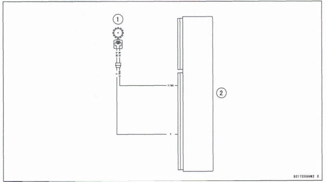
- Measure the output voltage at the gear position sensor in the same way as input voltage inspection, note the following.
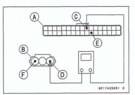
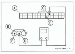
Connect the suitable measuring lead [A] between these connectors.
Main Harness [B]
Gear Position Sensor [C]
Digital Meter [D]
Gear Position Sensor Output Voltage
Connections to Adapter:
Digital Meter (+) → Y (sensor G) lead
Digital Meter (-) → BK (sensor BK) lead
- Measure the output voltage with the engine stopped and with the connector joined.
- Turn the Ignition switch on.
Output voltage 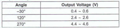
NOTE
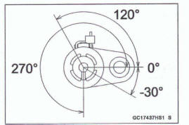
- This figure shows 270º.
- Rotate the gear position sensor, confirm the output voltage will be raise or lower.
Turn the ignition switch off.
- If the reading is out of the standard, replace the gear position sensor (see Gear Position Sensor Removal/Installation in the Electrical System chapter).
- If the reading is within the standard, remove the ECU and check the wiring for continuity between main harness connectors.
Disconnect the ECU and sensor connectors.
Wiring Continuity Inspection
ECU Connector [A] ←→
Gear Position Sensor Connector [B]
ECU Terminal 12 [C] ←→ Sensor Terminal [D]
ECU Terminal 28 [E] ←→ Sensor Terminal [F]
If the wiring is good, check the ECU for its ground and power supply (see ECU Paw Supply Inspection).
If the ground and power supply are good, replace the ECU (see ECU Removal/ Installation).
Gear Position Sensor Circuit
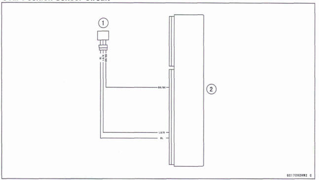
- Gear Position Sensor
- ECU
See also:
 Kawasaki Z400 - Service manual > Intake Air Temperature Sensor (Service Code 13) (DTC P0110, P0112)
Intake Air Temperature Sensor Removal/ Installation
Kawasaki Z400 - Service manual > Vehicle-down Sensor (Service Code 31) (DTC C0064)
This sensor has a weight [A] with two magnets inside, and sends a signal to the ECU. But when the motorcycle banks 60 ~ 70° or more to either side (in fact falls down), the weight turns and the signal changes. The ECU senses this change, and stops the fuel pump relay, the fuel injectors and the ignition system.
 Benelli Imperiale 400
 BMW F900XR
 Honda CB500X
 KTM 390 Adventure
 Triumph Street Triple S
 Yamaha MT-03
 Kawasaki Z400
 Triumph Street Triple S
 Yamaha MT-03