 Yamaha MT-03 - Service manual > Immobilizer system
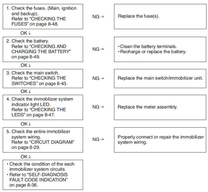
Circuit diagram
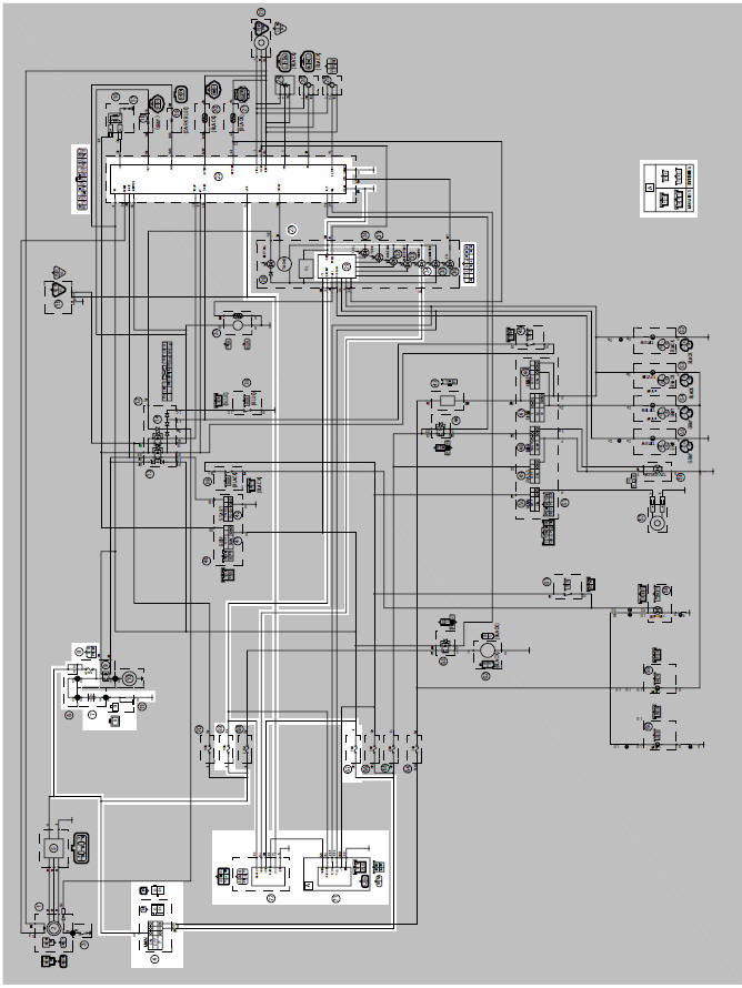
4. Main switch
7. Battery
8. Main fuse
22.ECU
27.Multi-function meter unit
34.Immobilizer system indicator light
67.Ignition fuse
69.Backup fuse (immobilizer unit, multi-function meter unit)
71.Anti-theft alarm (optional)
72.Immobilizer unit
General information
This vehicle is equipped with an immobilizer system to help prevent theft by re-registering codes in the standard keys. This system consists of the following:
- a code re-registering key (with a red bow)
- two standard keys (with a black bow) that can be re-registered with new codes
- a transponder (installed in the red key bow)
- an immobilizer unit
- the ECU
- an immobilizer system indicator light
The key with the red bow is used to register codes in each standard key. Do not use the key with the red bow for driving. It should only be used for re-registering new codes in the standard keys. The immobilizer system cannot be operated with a new key until the key registered with a code. If you lose the code re-registering key, the ECU and main switch (equipped with the immobilizer unit) need to be replaced.
Therefore, always use a standard key for driving. (See caution below.)
NOTE:
Each standard key is registered during production, therefore re-registering at purchase is not necessary.
CAUTION:
- DO NOT LOSE THE CODE RE-REGISTERING KEY! If the code re-registering key is lost, regis-tering new codes in the standard keys is impossible. The standard keys can still be used to start the vehicle. However, if code re-registering is required (e.g., if a new standard key is made or all keys are lost) the entire immobilizer system must be replaced. Therefore, it is highly recommended to use either standard key for driving, and to keep the code reregistering key in a safe place.
- Do not submerse the keys in water.
- Do not expose the keys to excessively high temperatures.
- Do not place the keys close to magnets (this includes, but is not limited to, products such as speakers, etc.).
- Do not place heavy items on the keys.
- Do not grind the keys or alter their shape.
- Do not disassemble the key bows.
- Do not put two keys of any immobilizer system on the same key ring.
- Keep the standard keys as well as other immobilizer system keys away from the code reregistering key.
- Keep other immobilizer system keys away from the main switch as they may cause signal interference.
Part replacement and key code registration Requirements
In the course of use, you may encounter the following cases where replacement of parts and registration of code re-registering/standard keys are required.
NOTE:
Each standard key is registered during production, therefore re-registering at purchase is not necessary.
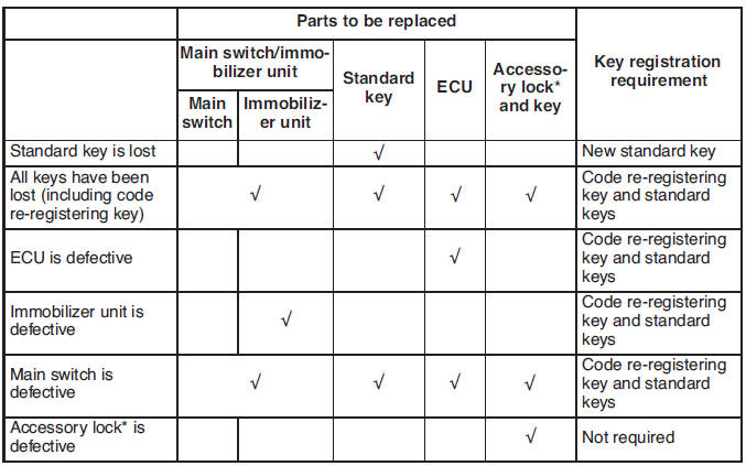
* Accessory locks mean the seat lock and fuel tank cap.
Code re-registering key registration:
When the immobilizer unit or ECU is replaced, the code re-registering key must be registered to the unit.
To register a code re-registering key: 1. Turn the main switch to "ON" with the code re-registering key.
NOTE:
Check that the immobilizer system indicator light comes on for one second, then goes off. When the immobilizer system indicator light goes off, the code re-registering key has been registered.
2. Check that the engine can be started.
3. Register the standard key, following the instructions in the section below.
Standby mode:
To enable the immobilizer system, turn the ignition key to "OFF". 30 seconds later, the indicator light will start flashing continuously in the standby flashing mode pattern for up to 24 hours. After that time, the indicator light will stop flashing, but the immobilizer system is still enabled.
Standby mode
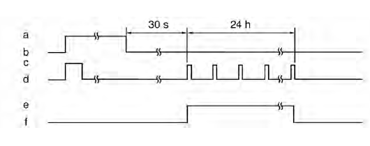
a. Main switch "ON"
b. Main switch "OFF"
c. LED on
d. LED off
e. Standby mode on
f. Standby mode off
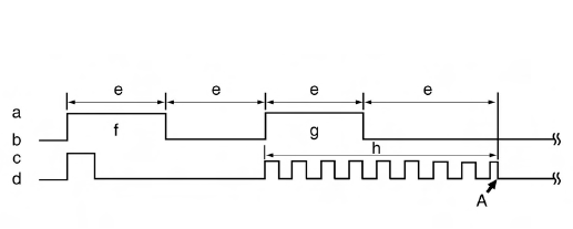
Standard key registration:
Standard key registration is required when a standard key is lost and needs to be replaced, or when the code re-registering key is re-registered after the immobilizer unit or ECU are replaced.
NOTE:
Do not start the engine with a standard key that has not been registered. If the main switch is turned "ON" with a standard key that has not been registered, the immobilizer system indicator light flashes to indicate fault code "52".
1. Check that the immobilizer system indicator light signals the standby mode.
2. Using the code re-registering key, turn the main switch to "ON", then "OFF", and then remove the key within 5 seconds.
3. Insert the first standard key to be registered into the main switch, then turn the key to "ON" within 5 seconds to activate the key registration mode.
NOTE:
The existing standard key code is erased from the memory when the key registration mode is activated.
When the key registration mode is activated, the immobilizer system indicator light flashes rapidly.
4. While the indicator light is flashing, turn the main switch to "OFF", remove the key, and within 5 seconds, insert the second standard key to be registered into the main switch.
NOTE:
If he immobilizer system indicator light stops flashing 5 seconds after the first standard key is registered, the registration mode is deactivated. If this occurs, the second standard key cannot be registered, and steps 2 to 4 need to be repeated to register both standard keys.
5. Turn the main switch to "ON".
NOTE:
When the indicator light goes off, the registration is complete.
6. Check that the engine can be started with the two registered standard keys.
Standard key registration
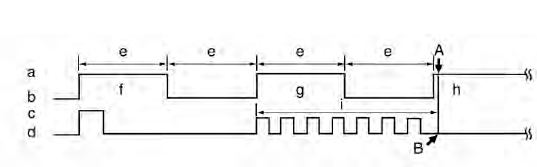
a. Main switch "ON"
b. Main switch "OFF"
c. LED on
d. LED off
e. Less than 5.0 s
f. Code re-registering key
g. First standard key
h. Second standard key
i. Registration mode
A. Registration of the second standard key is complete.
B. Immobilizer system indicator light stops flashing when the registration of the second standard key is complete.
Voiding the standard key code:
If a standard key has been lost, it is possible to disable its use by re-registering the remaining standard key. Standard key registration erases the stored standard key code from the memory, thus disabling the lost standard key.To re-register, refer to "Standard key registration".
Standard key code voiding method
a. Main switch "ON"
b. Main switch "OFF"
c. LED on
d. LED off
e. Less than 5.0 s
f. Code re-registering key
g. Remaining standard key
h. Registration mode
A. If the immobilizer system indicator light stops flashing 5 seconds after the first standard key is registered, the second standard key cannot be registered.
Troubleshooting
When the main switch is turned to "ON", the immobilizer system indicator light does not come on nor flashes.
NOTE:
- Before troubleshooting, remove the following part(s):
1. Seats
2. Side panels (left and right)
3. Fuel tank
4. Battery cover
Self-diagnosis fault code indication
When a system malfunction occurs, the fault code number is signaled by the immobilizer system indicator light.
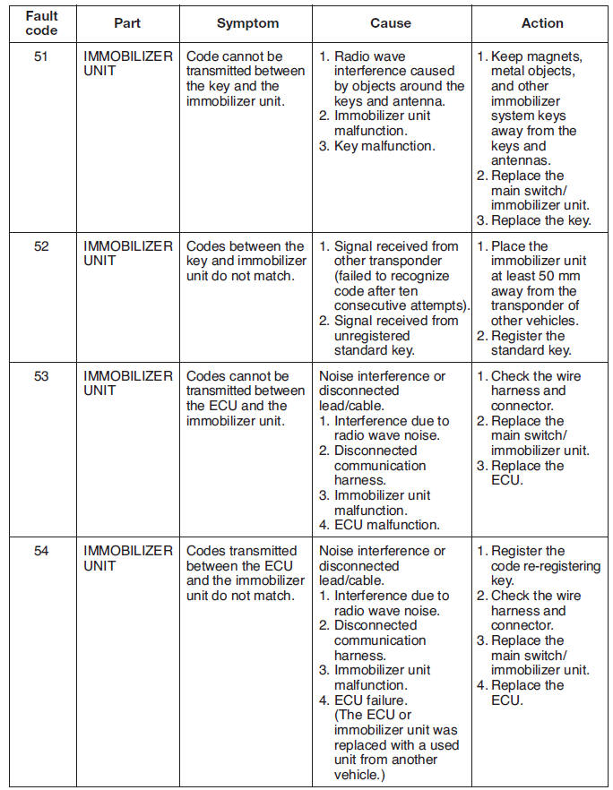
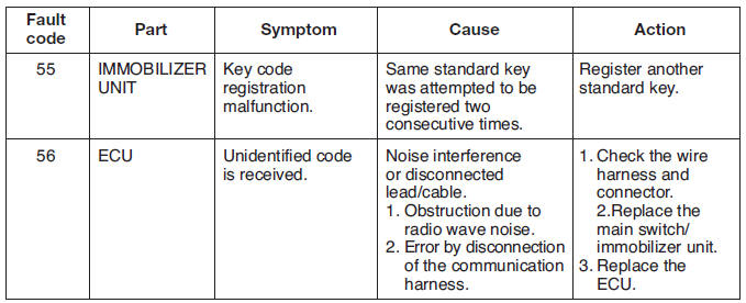
Immobilizer system indicator light fault code indication
Units of 10: Cycles of on for 1 second and off for 1.5 seconds.
Units of 1: Cycles of on for 0.5 second and off for 0.5 second.
Example: fault code 52
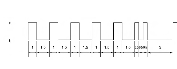
a. Light on
b. Light off
See also:
 Yamaha MT-03 - Service manual > Electric starting system
Circuit diagram 3. Neutral switch 4. Main switch
Yamaha MT-03 - Service manual > Electrical components
Starter relay Main fuse Battery Fuel pump Throttle position sensor Coolant temperature sensor Fuel injector ECU (electronic control unit) Lean angle cut-off switch Turn signal/hazard relay Headlight relay Radiator fan motor relay Relay unit Rectifier/regulator Sidestand switch Crankshaft position sensor Stator coil Horn Front brake light switch Right handlebar switch Clutch switch Left handlebar switch Main switch Immobilizer unit Ignition coil Plug cap Spark plug Intake air pressure sensor Fuse box Rear brake light switch Intake air temperature sensor Neutral switch Starter motor Speed sensor Radiator fan motor Air induction system solenoid
 Benelli Imperiale 400
 BMW F900XR
 Honda CB500X
 KTM 390 Adventure
 Triumph Street Triple S
 Yamaha MT-03
 Kawasaki Z400
 Triumph Street Triple S
 Yamaha MT-03