 Yamaha MT-03 - Service manual > Electric starting system
Circuit diagram
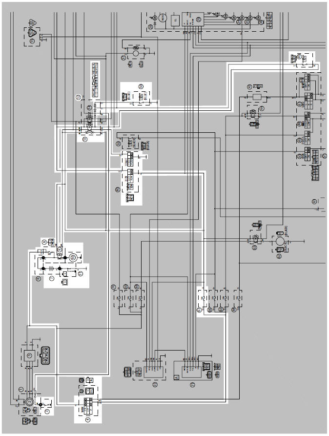
3. Neutral switch
4. Main switch
7. Battery
8. Main fuse
9. Starter relay
10.Starter motor
12.Relay unit
13.Starting circuit cut-off relay
38.Sidestand switch
41.Engine stop switch
42.Start switch
45.Clutch switch
67.Ignition fuse
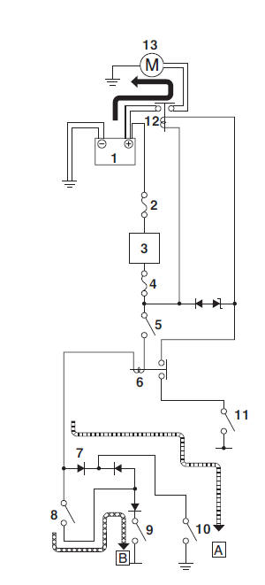
Starting circuit cut-off system operation
If the engine stop switch is set to "I" and the main switch is turned "ON" (both switch circuits are closed), the starter motor can only operate if at least one of the following conditions is met:
- The transmission is in neutral (the neutral switch circuit is closed).
- The clutch lever is pulled to the handlebar (the clutch switch circuit is closed) and the sidestand is up (the sidestand switch circuit is closed).
The starting circuit cut-off relay prevents the starter motor from operating
when neither of these conditions
has been met. In this instance, the starting circuit cut-off relay stays open so
current cannot
reach the starter motor. When at least one of the above conditions has been met,
the starting circuit
cut-off relay is closed and the engine can be started by pushing the start
switch " ".
".
 WHEN THE TRANSMISSION IS IN
NEUTRAL
WHEN THE TRANSMISSION IS IN
NEUTRAL
 WHEN THE SIDESTAND IS UP AND THE
CLUTCH LEVER IS PULLED TO THE
HANDLEBAR
WHEN THE SIDESTAND IS UP AND THE
CLUTCH LEVER IS PULLED TO THE
HANDLEBAR
- Battery
- Main fuse
- Main switch
- Ignition fuse
- Engine stop switch
- Relay unit (starting circuit cut-off relay)
- Relay unit (diode)
- Clutch switch
- Sidestand switch
- Neutral switch
- Start switch
- Starter relay
- Starter motor
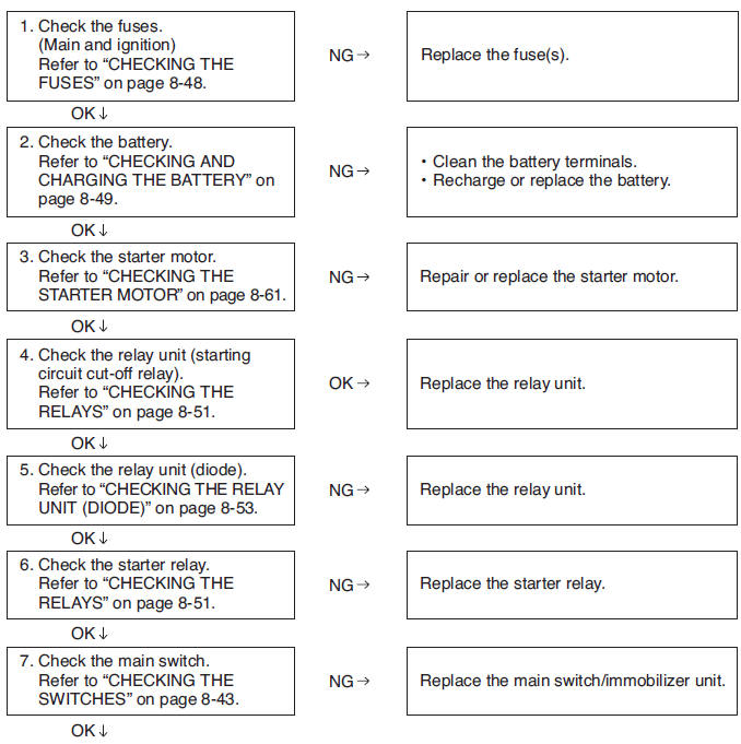
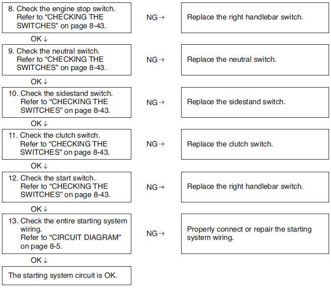
Troubleshooting
The starter motor fails to turn.
NOTE:
Before troubleshooting, remove the following part(s):
- Seats
- Side panels (left and right)
- Fuel tank
- Battery cover
Charging system
Circuit diagram
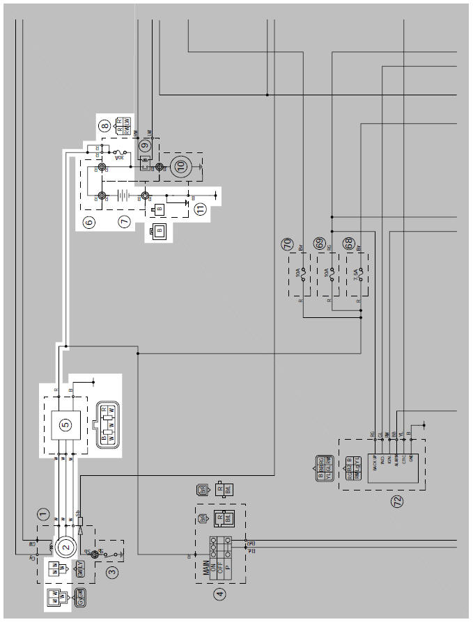
2. A.C. magneto
5. Rectifier/regulator
7. Battery
8. Main fuse
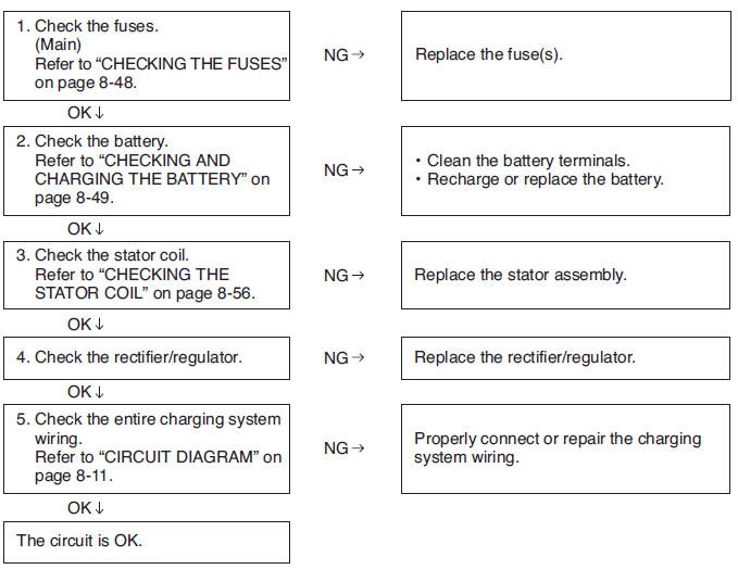
Troubleshooting
The battery is not being charged.
NOTE:
- Before troubleshooting, remove the following part(s):
- Seats
- Side panels (left and right)
- Fuel tank
- Battery cover
Lighting system
Circuit diagram
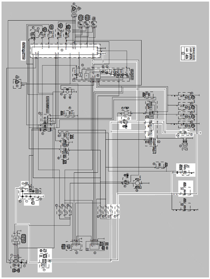
4. Main switch
7. Battery
8. Main fuse
22.ECU
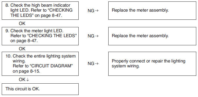
32.High beam indicator light
44.Headlight relay
48.Dimmer switch
49.Pass switch
56.Headlight
58.Tail/brake light
59.Auxiliary light
64.Parking lighting fuse
65.Headlight fuse
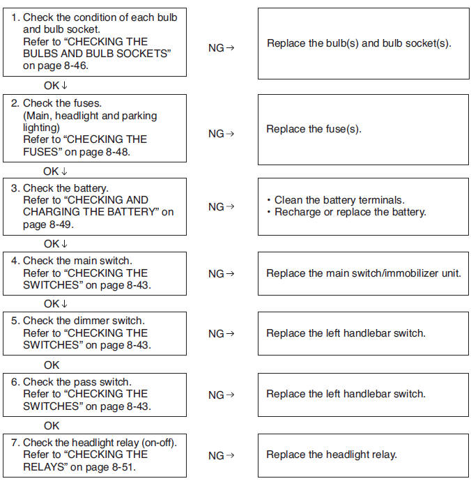
Troubleshooting
Any of the following fail to light: headlight (high beam), headlight (low beam), high beam indicator light, taillight, license plate light, auxiliary light or meter light.
NOTE:
- Before troubleshooting, remove the following part(s):
- Seats
- Side panels (left and right)
- Fuel tank
- Battery cover
- Headlight assembly
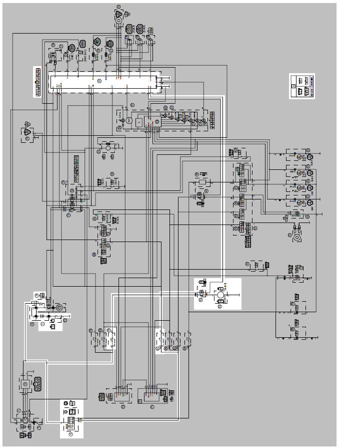
Signaling system
Circuit diagram
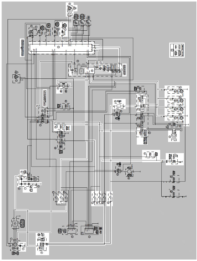
3. Neutral switch
4. Main switch
7. Battery
8. Main fuse
12.Relay unit
21.Coolant temperature sensor
22.ECU
23.Speed sensor
28.Neutral indicator light
29.Multi-function meter
30.Fuel level warning light
31.Turn signal indicator light
33.Coolant temperature warning light
36.Engine trouble warning light
37.Fuel pump
39.Front brake light switch
43.Turn signal/hazard relay
46.Hazard switch
47.Turn signal switch
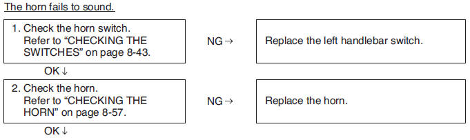
50.Horn switch
52.Rear turn signal light (right)
53.Front turn signal light (right)
54.Front turn signal light (left)
55.Rear turn signal light (left)
57.Horn
58.Tail/brake light
61.Rear brake light switch
64.Parking lighting fuse
66.Signaling system fuse
67.Ignition fuse
69.Backup fuse (immobilizer unit, multi-function meter unit)
TROUBLESHOOTING
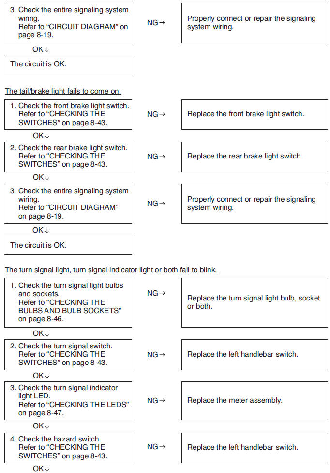
Any of the following fail to light: turn signal light, brake light or indicator light.
NOTE:
- Before troubleshooting, remove the following part(s):
- Seats
- Side panels (left and right)
- Fuel tank
- Battery cover
- Headlight assembly
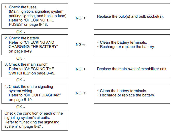
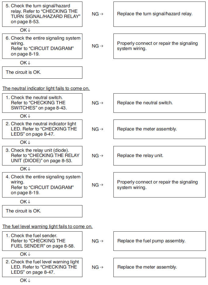
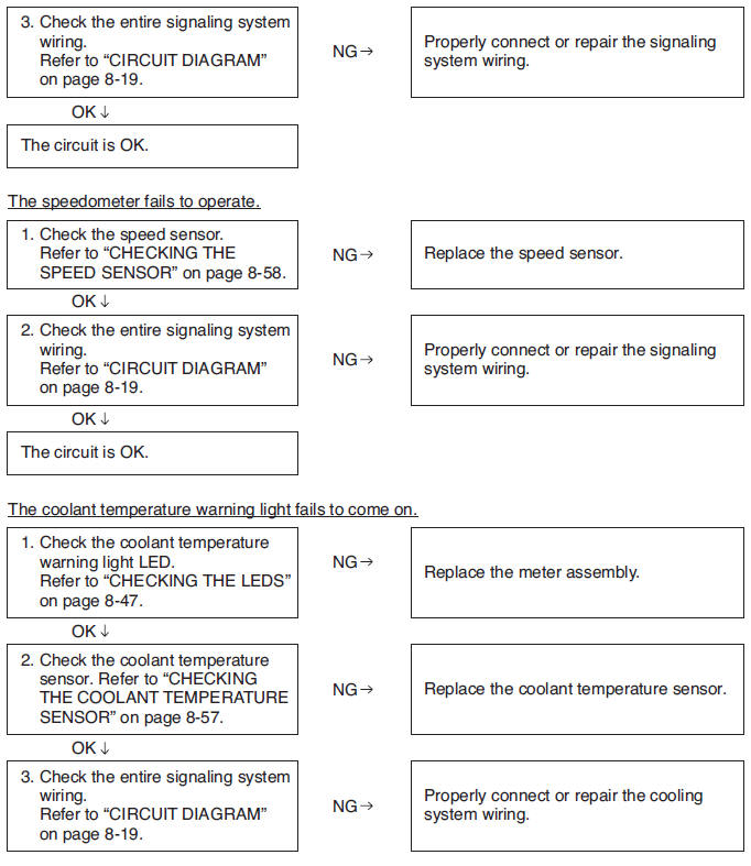
Checking the signaling system
Cooling system
Circuit diagram
4. Main switch
7. Battery
8. Main fuse
22.ECU
62.Radiator fan motor
63.Radiator fan motor relay
67.Ignition fuse
68.Radiator fan motor fuse
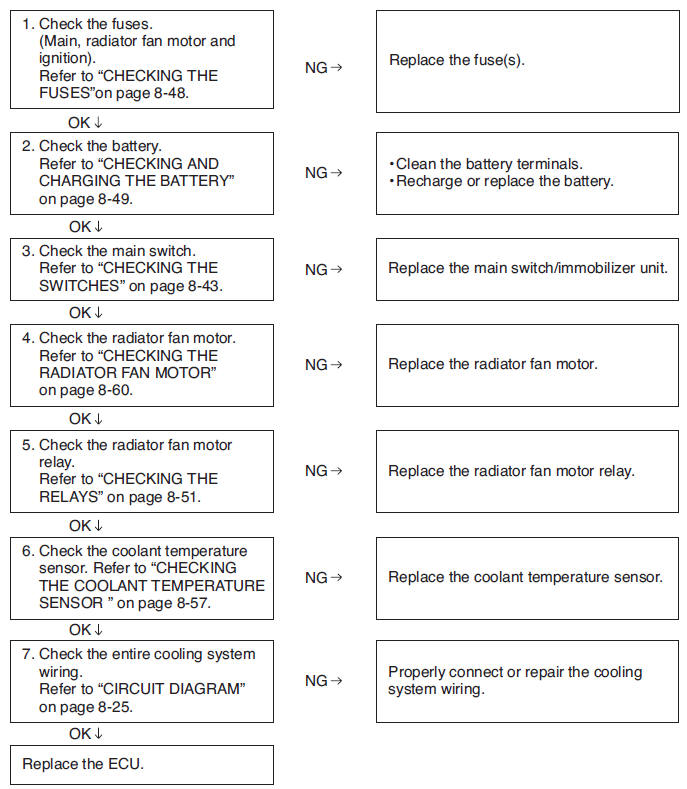
Troubleshooting
If the radiator fan motor fails to operate.
NOTE:
Before troubleshooting, remove the following part(s):
1. Seats
2. Side panels (left and right)
3. Fuel tank
4. Battery cover
See also:
 Yamaha MT-03 - Service manual > Electrical system
Ignition system Circuit diagram 1. Crankshaft position sensor
Yamaha MT-03 - Service manual > Immobilizer system
Circuit diagram 4. Main switch 7. Battery 8. Main fuse
 Benelli Imperiale 400
 BMW F900XR
 Honda CB500X
 KTM 390 Adventure
 Triumph Street Triple S
 Yamaha MT-03
 Kawasaki Z400
 Triumph Street Triple S
 Yamaha MT-03