 Kawasaki Z400 - Service manual > Fuel Pump
Fuel Pump Removal
WARNING
Gasoline Is extremely flammable and can be explosive under certain conditions, creating the potential for serious burns. Make sure the area is well ventilated and free from any source of flame or sparks; this includes any appliance with a pilot light. Do not smoke. Turn the Ignition switch off. Disconnect the battery (-) terminal. To avoid fuel spills, draw it from the tank when the engine Is cold. Be prepared for fuel spillage; any spilled fuel must be completely wiped up immediately.
NOTICE
Never drop the fuel pump especially on a hard surface.
Such a shock to the pump can damage it.
- Draw the fuel out from the fuel tank with a commercially available electric pump.
- Remove the fuel tank (see Fuel Tank Removal).
Be careful of fuel spillage from the fuel tank since fuel still remains in the fuel tank and fuel pump. Plug the fuel pipe of the fuel tank
- Turn the fuel tank upside down.
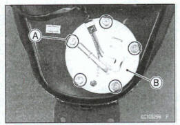
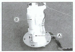
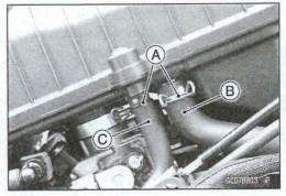
- Remove the fuel pump bolts [A], and take out the fuel Pump [B]
NOTICE
Do not pull the leads of the fuel pump. If they are pulled, the lead terminals may be damaged.
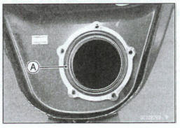
- Discard the fuel pump gasket [A].
Fuel Pump Installation
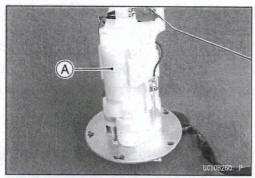
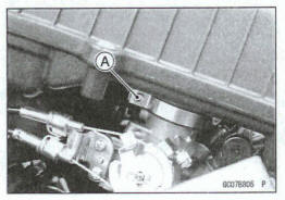
- Remove dirt or dust from the fuel pump [A] by lightly plying compressed air.
- Replace the fuel pump gasket with a new one.
NOTE
Be careful not to bend the fuel level sensor am.
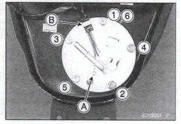
- Check that the fuel pump terminal [A] and clamp [B] are in place.
- Apply a non-permanent locking agent to the threads of the fuel pump bolts.
- Tighten the fuel pump bolts following the specified tightening sequence [1 ~ 6]temporarily.
- Tighten the fuel pump bolts with the specified toque by the same sequence.
Torque - Fuel Pump Bob: 9.8 N*m (1.0 kgf*m, 87 In-lb)
- Tighten the pump bolts again to check the tightness.
Fuel Pump Operation Inspection
NOTE
Be sure the battery is fully charged.
- Turn the engine stop switch to run position.
- Turn the ignition switch on and make sure that the fuel pump operates (make light sounds) for 3 seconds, and then stops.
- Turn the ignition switch off.
If the pump does not operate as described above, check the operating voltage (see Fuel Pump Operating Voltage Inspection).
Fuel Pump Operating Voltage Inspection
NOTE
Be sure the battery is fully charged.
- Turn the ignition switch off.
- Remove the right middle fairing (see Middle Fairing Removal in the Frame chapter).
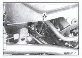
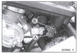
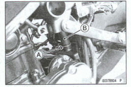
- Disconnect the fuel pump bad connector [A].
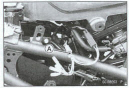
- Connect the measuring adapter [A] between fuel pump lead connectors.
Special Toll- Oxygen Sensor Measuring Adapter: 57001 -1 682
- Connect a digital meter to the measuring adapter leads
Fuel Pump Operating Voltage
Connections to Adapter:
Digital Meter (+) → BR (pump BK/Y) lead
Digital Meter (-) → W (pump BK/W) lead
- Measure the operating voltage with engine stopped and with the connector joined.
- Turn the engine stop switch to run position.
- Turn the ignition switch on.
Operating Voltage Standard: Battery Voltage for 3 seconds, and then 0 V
- Turn the ignition switch off.
*If the reading stays on battery voltage and never shows 0 V, check the fuel pump relay (see Relay Circuit Inspection in the Electrical System chapter).
*If the fuel pump relay is normal, check the ECU for its ground and power supply (see ECU Power Supply Inspection).
*If the ground and power supply are good, replace the ECU (see ECU Removal/Installation).
*If there is still no battery voltage, check the fuel pump relay (see Relay Circuit Inspection in the Electrical System chapter).
*If the fuel pump relay is normal, check the wiring for continuity (see Fuel Pump Circuit).
*If the wiring is good, check the ECU for its ground and power supply (see ECU Power Supply Inspection).
*If the ground and power supply are good, replace the ECU (see ECU Removal/Installation).
*If the reading is in specification, but the pump does not operate, replace the fuel pump (see Fuel Pump Removal/Installation).
Pressure Regulator Removal
The pressure regulator [A] is built into the fuel pump [B] and can not be removed.
Fuel Pump Relay Removal/Installation
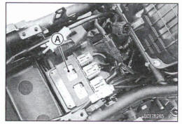
The fuel pump relay is built in the relay box [A].
- Refer to the Relay Box Removal in the Electrical System chapter.
Fuel Pump Relay Inspection
- Refer to the Relay Circuit Inspection in the Electrical System chapter
Fuel Pump Circuit
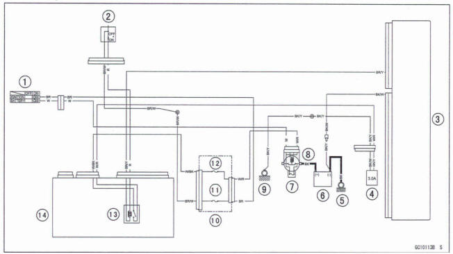
- Ignition Switch
- Engine Stop Switch
- ECU
- Fuel Pump
- Engine Ground
- Battery
- Main Fuse 30 A
- Starter Relay
- Frame Ground (2)
- Fuse Box (1)
- Ignition Fuse 10 A
- ECU Fuse 15 A
- Fuel Pump Relay
- Relay Box
Throttle Grip and Cables
Throttle Grip Free Play Inspection
- Refer to the Throttle Control System Inspection in the Periodic Maintenance chapter
Throttle Grip Free Play Adjustment
- Refer to the Throttle Control System Inspection in the periodic Maintenance chapter.
Throttle Cable Installation
- Install the throttle cables in accordance with the Cable, Wire, and Hose Routing section in the Appendix chapter.
- Install the lower ends of the throttle cables in the throttle pulley on the throttle body assy after installing the upper ends of the throttle cables in the grip.
- After installation, adjust each cable properly (see Throttle Control System Inspection in the Periodic Maintenance chapter)
WARNING
Operation with incorrectly routed or improperly adjusted cables could result In an unsafe riding condition.
Be sure the cables are routed correctly end properly adjusted.
Throttle Cable Lubrication
- Refer to the Chassis Parts Lubrication in the Periodic Maintenance chapter.
Throttle Body Assy
Idle Speed Inspection/Adjustment
- Refer to the ldle Speed Inspection/Adjustment in the Periodic Maintenance chapter.
Throttle Bore Cleaning
- Check the throttle bore for cleanliness as follows
Remove the throttle body assy (see Throttle Body Assy Removal).
Check the throttle valves and throttle bores for carbon deposits by opening the throttle valves.
*If any carbon accumulates, wipe the carbon off the throttle bores around the throttle bores and the throttle valves, using a cotton pad penetrated with a high flash-point solvent.
Synchronization Inspsetion/Adjustment
Refer to the Engine Vacuum Synchronization Inspection in the Periodic Maintenance chapter
Throttle Body Assy Removal
WARNING
Gasoline is extremely flammable and can be explosive under certain conditions, creating the potential for serious burns. Make sure the area is well ventilated and free from any source of flame or sparks; this Includes any appliance with a pilot light. Do not smoke. Turn the ignition switch off. Be prepared for fuel spillage; any spilled fuel must be completely wiped up immediately.
Notice
Never drop the throttle body assy especially on a hard surface. Such a shock to the body assy can damage it.
- Remove: Air Cleaner Housing (see Air Cleaner Housing Removal) Fuel Hose (see Fuel Hose Replacement in the Periodic Maintenance chapter)
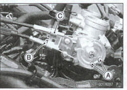
- Disconnect: Throttle Sensor Connector IA] Idle Speed Control Valve Actuator or Connector [B] Intake Air Pressure Sensor Connector [C] Fuel Injector Connectors Connector [D]
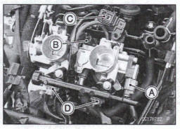
For evaporative emission control system equipped models, disconnect the vacuum hose [A].
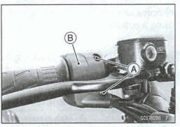
- Remove: Switch Housing Screws [A]
- Separate right switch housing [B].
- Disconnect the throttle cable upper ends.
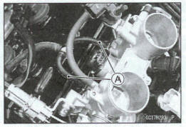
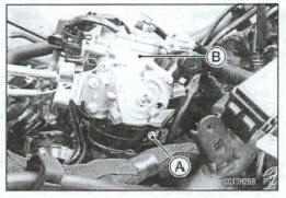
Disconnect the throttle cable lower ends [A].
Remove the damp [B].
Remove the throttle cables from the throttle cable holder [C].
- Loosen: Throttle Body Assy Hokier Clamp Screw [A] (Both Sides)
- Remove the throttle body assy [B].
- After removing the throttle body assy, stuff pieces of lintfree, clean cloth into the throttle body assy holders.
Notice
If dirt gets into the engine, excessive engine wear and possible engine damage will occur.
Throttle Body Assy Installation
- Be sure to position the throttle body assy holder damp in original position (see Throttle Body Assy Holder Installation in the Engine Top End chapter).
- Install the throttle body assy to the throttle body assy holders.
- Tighten:
Toque - Throttle Body Assy Holder Clamp Bob: 2.0 N*m (0.20 kgf*m, 18 in*lb)
The accelerator cable has a clamp [C].
- Install the damp securely.
- Install the right switch housing (see Handlebar Installation in the steering chapter).
- Turn the throttle grip and make sure that the throttle pulley moves smoothly and return by spring force.
- Run the leads and hoses correctly (see Cable, Wire, and Hose Routing section in the Appendix chapter).
- Install the removed parts (see appropriate chapters).
- Adjust Throttle Grip Free Play (see Throttle Control System Inspection in the Periodic Maintenance chapter)
Throttle Body Assy Disassembly
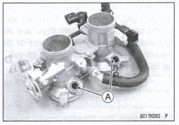
Notice
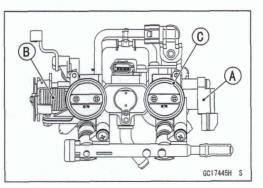
Do not remove, disassemble or adjust the throttle sensor [A], throttle link mechanism [B] and throttle body assy [C], because they are adjusted or set at the manufacturer. Adjustment of these parts could result in poor performance, requiring replacement of the throttle body assy.
Notice
Never drop the throttle body assy especially on a hard surface. Such a shock to the body assy can damage it.
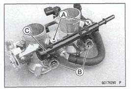
- Remove: Throttle Body Assy (see Throttle Body Assy Removal)
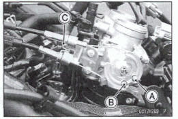
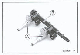
- Remove the delivery pipe mounting screws [A].
- Pull out the fuel injectors [B] from the throttle body assy together with the delivery pipe [C].
NOTE
Do not damage the insertion portions of the fuel injectors when they am pulled out from the throttle body
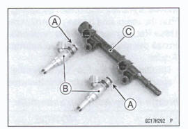
- Remove the fuel injectors [A] from the delivery pipe [B].
NOTE
Do not damage the insertion portions of the fuel injectors when they are pulled out from the delivery pipe.
NOTICE
Never drop the fuel injector especially on a hard sum. Such e shock to the fuel injector can damage it.
Throttle Body Assy Assembly
- Before assembling, blow away dirt or dust from the throttle body and delivery pipe by applying compressed air.
- Replace the O-rings [A] of each fuel injector [B] with new ones.
- Apply engine oil to the new O-rings, insert them to the delivery pipe [C] and confirm whether the fuel injectors turn smoothly or not.
- Replace the dust seals [A] with new ones.
- Apply engine oil to the new dust seals.
- Install the fuel injectors along with the delivery pipe to the throttle body.
- Tighten:
Toque - Delivery Pipe Mounting Screws: 3.5 Nm (0.38 kgf-m, 31 in-lb)
- Install: Throttle Body Assy (see Throttle Body Assy Installation
Air Cleaner
Air Cleaner Element Removal/Installation
- Refer to the Air Cleaner Element Replacement in the Periodic Maintenance chapter.
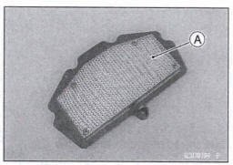
Air Cleaner Element Inspection
- Remove the air cleaner element (see Air Cleaner Element Replacement in the Periodic Maintenance chapter).
- Visually check the dement [A] for tears or breaks
*If the element has any tears or breaks, replace the element.
Air Cleaner Oil Draining
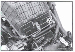
A drain cap is connected to the bottom of the air cleaner housing to drain water or oil accumulated in the cleaner part.
- Visually check the drain cap [A], if the water or oil accumulates h the cap
*If any water or oil accumulates in the drain cap, slide the clamp [B] and move the cap from the air cleaner housing and drain it.
Warning
Oil on tires will make them slippery and can cause an accident and injury. Be sure to reinstall the cap in the air cleaner housing after draining.
Air Cleaner Housing Removal
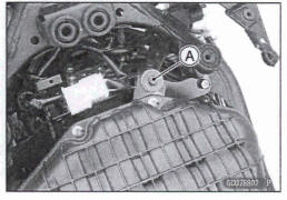
- Remove: Air Cleaner Housing Mounting Bolt [A]
- Slide the damps [A].
- Disconnect: Air Switching Valve Hose [B] Intake Air Hose [C]
- Slide the clamp [A].
- Disconnect the breather hose [B].
- Loosen the air cleaner housing clamp bolt [A] on both sides
- Remove the air cleaner housing
Air Cleaner Housing Installation
- Installation is the reverse of removal.
- Run the hose, cable and leads correctly (see Cable, Wire, and Hose Rang section in the Appendix chapter).
- Tighten:
Torque Air Cleaner Housing Clamp Bolts: 2.0 N-m (0.20 kgf*m, 18 in-lb) Air Cleaner Housing Mounting Bolt: 9.8 Nm (1.0 kgf-m, 87 In-lb)
- Install the removed parts (see appropriate chapters).
See also:
 Kawasaki Z400 - Service manual > ECU
ECU Identification Most countries have their own regulations, so each ECU has different characteristic. So, do not confuse ECU with each other and use only the ECU for your model. Otherwise, the motorcycle cannot clear the regulation.
Kawasaki Z400 - Service manual > Fuel Tank
Fuel Tank Removal WARNING Gasoline is extremely flammable and can be explosive under certain conditions, creating the potential for serious bums. Make sum the area Is well ventilated and free from any source of flame or sparks; this includes any appliance with a pilot light. Do not smoke. Turn the ignition switch off. Disconnect the battery (-)terminal. To avoid fuel spills, draw it from the tank when the engine b cold. E4a prepared for fuel spillage; any spilled fuel must be completely wiped up immediately. Turn the ignition switch off. Wait until the engine cools down. Disconnect the battery (-) terminal (see Battery Removal in the Electrical System chapter). Remove: Seats (Rear/Front Seat Removal in the Frame chapter) Middle Fairings (see Middle Fairing Removal in the Frame chapter) Remove the bolt [A] on both sides. Clear the projection [B] of the upper inner fairing to the grommet on both sides. Slide the damps [A]. Disconnect: Drain Hose [B] Breather Hose [C] Remove: Fuel Tank Bolts [A] Bracket [B] Disconnect the fuel pump lead connector [A]. Open the fuel tank cap [A] to lower the pressure In the tank. During tank removal, keep the tank cap open to release pressure in the tank. This makes fuel spillage less. Draw the fuel out from the fuel tank with a commercially available pump [A].
 Benelli Imperiale 400
 BMW F900XR
 Honda CB500X
 KTM 390 Adventure
 Triumph Street Triple S
 Yamaha MT-03
 Kawasaki Z400
 Triumph Street Triple S
 Yamaha MT-03