 Kawasaki Z400 - Service manual > Stick Coils #1, #2 (Service Code 51, 52) (DTC P0351, P0352)
Inspect the eligible stick coil according to the following service code or DTC.
Service Code 51/DTC PO351→ Stick Coil #1
Service Code 52/DTC PO352 →P Stick Coil #2
Stick Coil Removal/Installation
- Refer to the Stick Coil Removal/Installation in the Electrical System chapter.
Stick Coil Primary Winding Resistance Inspection
- Refer to the Stick Coil Inspection in the Electrical System chapter.
If the reading is within the standard, check the input voltage (see Stick Coil Input Voltage Inspection).
Stick Coil Input Voltage Inspection
NOTE
Be sure the battery is fully charged.
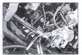
- Turn the ignition switch off.
- Remove: Air Cleaner Housing (see Air Cleaner Housing Removal)
- Disconnect the stick coil connector and connect the measuring
adapter [A] between these connectors as shown.
Main Harness [B].
Stick Coil [C]
Special Tool - Measuring Adaptor: 57001 -1700
- Connect a digital meter [O] to the measuring adapter leads.
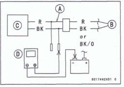
Stick Coil Input Voltage
Connections to Adaptor:
For Stick Coil #l
Digital Meter (+)→ BK (stick coil BK)
Digital Meter (-) → Battery (-) Terminal
FW stick coil m
Digital Meter (+) →BK (stick coil BK/O)
Digital Meter (-) → Battery (-) Terminal
- Measure the input voltage to each primary winding of the stick coils with the engine stopped and with the connectors joined.
- Turn the engine stop switch to run position.
- Turn the ignition switch on.
Input Voltage Standard: Battery Voltage
- Turn the ignition switch off.
If the input voltage is out of the standard, check the wiring for continuity (see Stick Coil Circuit).
*If the wiring is good, check the ECU for its ground and power supply (see ECU Power Supply Inspection).
*If the ground and power supply are good, replace the ECU (see ECU Removal/Installation).
*If the input voltage is within the standard, check the ECU for its ground and power supply (see ECU Power Supply Inspection).
*If the ground and power supply are good, replace the ECU (see ECU Removal/Installation).
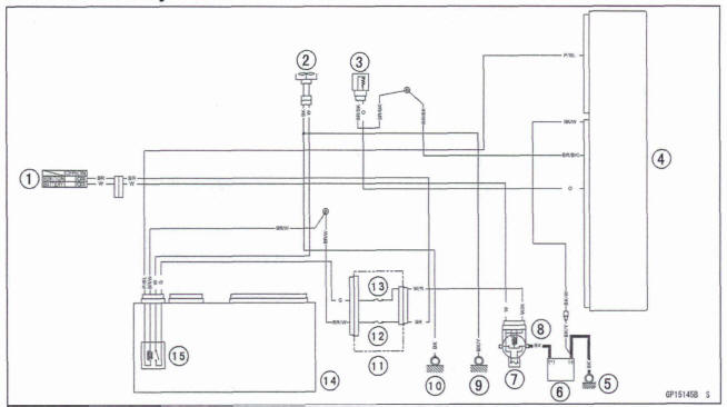
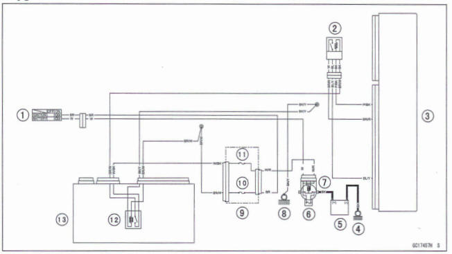
Stick Coil Circuit
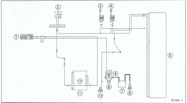
- Ignition Switch
- Engine Stop Switch
- Stick Coil #1
- Stick Coil #2
- ECU
- Engine Ground
- Battery
- Main Fuse 30 A
- Starter Relay
- Frame Ground (2)
- Fuse Box (1)
- Ignition Fuse 10 A
Radiator Fan Relay (Service Code 56) (DTC P0480)
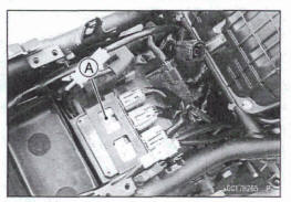
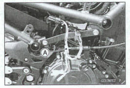
Radiator Fan Relay Removal/Installation
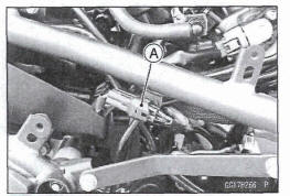
- The radiator fan relay is built in the relay box [A].
Refer to the Relay Box Removal in the Electrical System chapter.
Radiator Fan Relay Inspection
- Refer to the Relay Circuit Inspection in the Electrical System chapter
*If the radiator fan relay normal, check the wiring for continuity (see Radiator Fan Relay Circuit).
*If the wiring is good, check the ECU for its ground and power supply (see ECU Power Supply Inspection).
*If the ground and power supply are good, replace the ECU (see ECU Removal/Installation).
Radiator Fan Relay Circuit
- Ignition Switch
- Fan Motor
- Water Temperature Sensor
- ECU
- Engine Ground
- Battery
- Main Fuse 30 A
- Starter Relay
- Frame Ground (6)
- Frame Ground (1)
- Fuse Box (1 )
- Ignition Fuse 10 A
- Fan Fuse 15 A
- Relay Box
- Fan Relay
Air Switching Valve (Service Code 64) (DTC P0410)
Air Switching Valve Removal/Installation
- Refer to the Air Switching Valve Removal/Installation in the Engine Top End chapter
Air Switching Valve inspection
- Refer to the Air Switching Valve Unit Test in the Electrical System chapter.
*If the air switching valve is normal, check the wiring for continuity (see Air Switching Valve Circuit).
*If the wiring is good, check the ECU for its ground and power supply (see ECU Power Supply Inspection).
*If the ground and power supply are good, replace the ECU (see ECU Removal/Installation).
Air Switching Valve Circuit
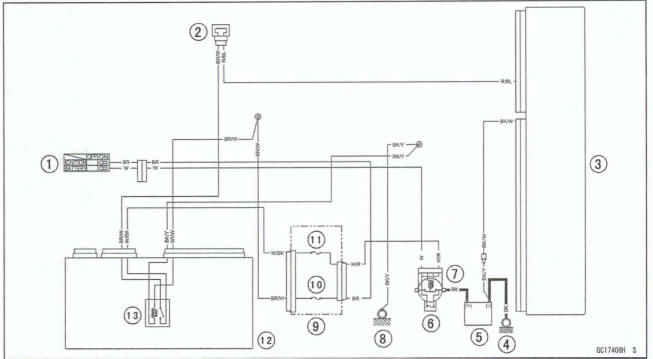
- Ignition Switch
- Air Switching Valve
- ECU
- Engine Ground
- Battery
- Main Fuse 30 A
- Starter Relay
- Frame Ground (2)
- Fuse Box (1)
- Ignition Fuse 10 A
- ECU Fuse 15 A
- Relay Box
- ECU Main Relay
Oxygen Sensor Heater (Service Code 67) (DTC P0030)
Oxygen Sensor Heater Removal/Installation
The oxygen sensor heater is built in the oxygen sensor.
So, the heater itself can not be removed. Remove the oxygen sensor (see Oxygen Sensor Removal in the Electrical System chapter).
Oxygen Sensor Heater Resistance Inspection
- Turn the ignition switch off.
- Remove the right middle fairing (see Middle Fairing Removal in the Frame chapter).
- Disconnect the oxygen sensor lead connector [A].
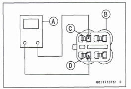
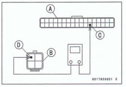
- Connect a digital meter [A] to the oxygen sensor lead connector [B].
- Measure the oxygen sensor heater resistance.
Oxygen Sensor Heaters Resistance
Connections: BK lead [C] ←→BK lead [D]
Standard: 5.49 ~ 6.91
 @20º C (68ºF)
*If the reading is out of the standard, replace the sensor (see Oxygen Sensor Removal/Installation in the Electrical System chapter).
*If the reading is within the standard, check the power source voltage (see Oxygen Sensor Heater Power Source Voltage Inspection).
Oxygen Sensor Heater Power Source Voltage Inspection
NOTE
Be sure the battery is fully charged.
- Turn the ignition switch off.
- Remove the right middle fairing (see Middle Fairing Removal in the Frame chapter).
- Disconnect the oxygen sensor lead connector and connect the measuring adapter [A] between these connectors.
Special Tool - Oxygen Sensor Measuring Adapter. 57001 -1 682
- Connect a digital meter to the measuring adapter lead.
Oxygen Sensor Power Source Voltage Connections to Adaptor.
Digital Meter (+) → W (main harness BR/W) lead
Digital Meter (-) → Frame Ground Terminal
Measure the power source voltage with the engine stopped and with the connector joined.
- Turn the ignition switch on
- Turn the ignition switch off.
If the reading is in specification, but the problem still exists, replace the ECU (see ECU Removal/Installation).
If the reading is out of the standard, check the following.
ECU Fuse 15 A (see Fuse Inspection in the Electrical system Power Source Wiring (see Oxygen Sensor Circuit)
If the fuse and wiring are good, mv8 the ECU and check the wiring for continuity between main harness connectors.
Disconnect the ECU and sensor connectors
Wiring Continuity Inspection
ECU Connector [A]
Oxygen Sensor Connector [B]
ECU Terminal 29 [C] Sensor Terminal
*If the wiring is good, check the ECU for its ground and power supply (see ECU Power Supply Inspection).
*If the ground and power supply are good, replace the ECU (see ECU Removal/Installation).
Oxygen Sensor Circuit
- Ignition Switch
- Oxygen Sensor
- ECU
- Engine Ground
- Battery
- Main Fuse 30 A
- Starter Relay
- Frame Ground (2)
- Fuse Box (1)
- Ignition Fuse 10 A
- ECU Fuse 15 A
- ECU Main Relay
- Relay Box
Fuel Supply System (Service Code 94) (DTC P0170
Fuel Supply System Inspection
NOTE
If the motorcycle has any other service code, first inspect the other service code.
- Inspect the general fuel system (throttle body assy, air cleaner, fuel tank etc.).
*If the general fuel system is good, check the ECU for its ground and power supply (see ECU Power Supply Inspection).
*If the ground and 'power supply are good, replace the ECU (see ECU Removal/Installation).
See also:
 Kawasaki Z400 - Service manual > Fuel Injectors (Service Code 41, 42) (DTC P0201, P0202)
Inspect the eligible fuel injector according to the following service code or DTC. Service Code 41/DTC PO201→ Fuel Injector #1
Kawasaki Z400 - Service manual > Idle Speed Control Valve Actuator (Service Code 1 C) (DTC P0508, P0509,
PO518)
Idle Speed Control Valve Actuator Removal Remove: Throttle Body Assy (see Throttle Body Assy Removal) Disconnect the intake air pressure hose [A]. Remove: Idle Speed Control Valve Actuator Screw [B] Prate [C] Idle Speed Control Valve Actuator [D] Spring
 Benelli Imperiale 400
 BMW F900XR
 Honda CB500X
 KTM 390 Adventure
 Triumph Street Triple S
 Yamaha MT-03
 Kawasaki Z400
 Triumph Street Triple S
 Yamaha MT-03