 Triumph Street Triple S - Service manual > Throttle Cable
Adjustment
Note:
- Minor adjustments to the opening cable can be made using the adjuster near the throttle grip end of the throttle. Where a correct setting cannot be achieved this way, the adjusters at the throttle end of both cables must be used. The opening cable must be set first followed by the closing cable.
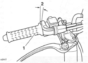
- Throttle grip
- Correct setting, 2-3 mm
1. Remove the rider's seat.
2. Disconnect the battery, negative (black) lead first.
3. Set the 'opening' cable adjuster at the throttle grip end such that it has an equal amount of adjustment in each direction. Tighten the locknut.
4. Remove the fuel tank.
5. Remove the airbox.
6. Set the 'opening' cable adjuster at the throttle body end to give 2-3 mm of play at the throttle grip.
Tighten the locknut.
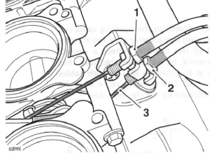
- 'Opening Cable Adjuster (Throttle End)
- 'Closing' Cable Adjuster (Throttle End)
- Closing cable - free play measurement point
7. With the throttle fully closed, ensure that there is 2-3 mm of free play in the 'closing' cable. Adjust if necessary ensuring that the locknut is secure afterwards.
Warning: Operation of the motorcycle with incorrectly adjusted, incorrectly routed or damaged throttle cables could interfere with the operation of the brakes, clutch or the throttle itself. Any of these conditions could result in loss of motorcycle control and an accident.
Warning: Move the handlebars to left and right full lock while checking that cables and harnesses do not bind. Cables or harness that bind will restrict the steering and may ca u se loss of motorcycle control and an accident.
Warning: Ensure that the adjuster locknuts are tightened. A loose throttle cable adjuster could cause the throttle to stick leading to loss of motorcycle control and an accident.
8. Refit the airbox.
9. Refit the fuel tank.
10. Reconnect the battery, positive (red) lead first.
11. Refit the rider's seat.
Removal
Note:
- Before beginning to remove the throttle cables, note the exact routing and location of both cables to help ensure that they are returned to the same locations and routing on assembly.
1. Remove the rider's seat.
2. Disconnect the battery, negative (black) lead first.
3. Remove the fuel tank.
4. Remove the airbox.
5. Detach the throttle bodies.
6. Slacken the adjuster locknuts at the throttle body end of the cables such that they will allow the outer cables to be detached from the cable bracket.
7. Detach the inner cable nipples from the throttle cam.
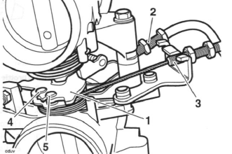
- Throttle cam
- Opening cable
- Closing cable
- Opening cable nipple
- Closing cable nipple
8. At the throttle grip end, slide off the rubber boot and release the screws which secure the two halves of the throttle grip guide to each other.
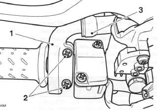
- Throttle grip guide
- Screws
- Rubber boot
9. Separate the two halves of the guide then release the inner cables from the throttle grip.
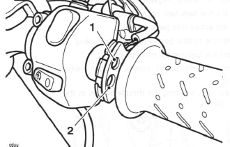
- Opening cable
- Closing cable
10. Detach the cables from the motorcycle.
Inspection
1. Check that both the throttle cables operate smoothly, without sticking or binding. Replace the cables if there is any doubt as to their correct operation.
Installation
1. Locate the cables to the frame following the routing noted during removal.
2. Engage the inner cable nipples to the throttle grip, ensuring the 'opening' cable is located in the upper slot in the throttle grip, and the 'closing' cable is located to the lower slot.
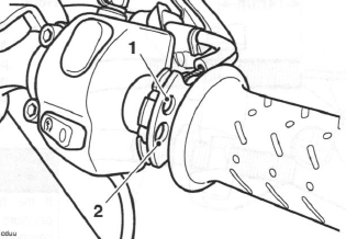
- Opening cable
- Closing cable
3. Assemble the two halves of the cable guide ensuring that the outer cables are correctly located in the guide and the guide is positioned on the handlebars as noted prior to removal. Fit and tighten the two screws to 4 Nm.
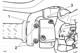
- Throttle grip guide
- Screws
- Rubber boot
4. Refit the boot.
5. Attach the other end of the inner cables to the throttle cam ensuring the 'opening' cable is fitted to the top of the cam and the 'closing' cable to the bottom.
6. Locate the outer cables to the bracket and adjust until the start of the thread is 14 mm away from the back of the throttle cable bracket. Secure the adjuster and locknuts.
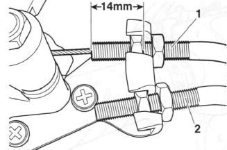
- Opening cable
- Closing cable
7. Refit the throttle bodies.
8. Set the throttle cable adjustment.
9. Refit the airbox.
10. Refit the fuel tank.
11. Reconnect the battery, positive (red) lead first.
12. Refit the rider's seat.
Throttle Bodies/Injectors
Removal
Note:
- Because fuel stored in the fuel rail will be at 3 bar pressure, it is essential that the fuel pressure is reduced before any dismantling of the fuel rail takes place. To reduce pressure, briefly crank the engine with the fuel pump disconnected.
Warning: If the fuel rail is dismantled without first reducing pressure fuel may escape causing clothing and components to be coated with fuel.
This would represent a serious fire hazard which could lead to burn injuries and damage to property.
1. Remove the rider's seat.
2. Disconnect the battery, negative (black) lead first.
3. Remove the fuel tank.
4. Remove the airbox.
5. Disconnect the throttle position sensor multi-plug.
6. Disconnect the fuel injector multi-plugs.
7. Disconnect the idle speed control stepper motor multi-plug.
8. Release the clips securing the throttle bodies to the transition pieces.
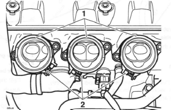
- Transition piece (one per cylinder)
- Clip location (throttle bodies removed for clarity)
9. Ease the throttle bodies from the transition pieces and lay the assembly carefully on the cam cover.
10. Release both throttle cables from the throttle cam.
11. Remove the throttle bodies.
12. If required, release the screws securing the fuel rail to the throttle bodies.
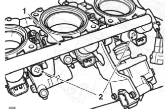
- Fuel rail
- Fuel rail screws
13. Ease the fuel rail and injectors from the throttle bodies.
14. To detach the injectors from the fuel rail, gently ease the injector from the rail.
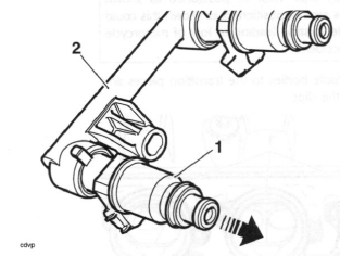
- Injector
- Fuel rail
15. To detach the transition pieces from the head, release the screws, raise the transition pieces and collect the O-rings.
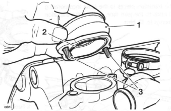
- Transition piece
- O-ring
- Fixings
Inspection
1. Check all joints and seals for splits, cuts and damage.
2. Check the throttles for sticking, loose or damaged throttle plates.
3. Check the transition piece O-rings for damage.
Installation
1. Thoroughly clean the transition piece to cylinder head mating faces.
2. Refit the transition pieces to the head incorporating new O-rings to the joint face. Tighten the transition piece fixings to 12 Nm.
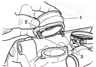
- Transition piece
- O-ring
- Fixings
3. If the injectors have been removed from the fuel rail, refit them to the rail, ensuring the injector locating peg is fully engaged in the slot in the rail.
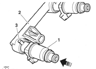
- Injector
- Fuel rail
- Locating peg
4. Check the injector O-rings for splits and other damage. Replace as necessary.
5. Refit the injectors and fuel rail to the throttle bodies.
Tighten the fuel rail screws to 3.5 Nm.
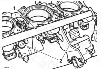
- Fuel rail
- Fuel rail screws
6. Re-attach the throttle cables.
Warning: The throttle body clips must be positioned as shown below. If the clips are not positioned as shown this could cause the throttle to stick, leading to loss of motorcycle control and an accident.
7. Refit the throttle bodies to the transition pieces and secure with the clips.
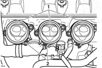
- Transition piece (one per cylinder)
- Clip location (throttle bodies removed for clarity)
8. Adjust the throttle cables.
9. Reconnect the idle speed control stepper motor multi-plug.
10. Reconnect the fuel injector multi-plugs.
11. Reconnect the throttle position sensor multi-plug.
12. Refit the airbox.
13. Refit the fuel tank.
14. Reconnect the battery, positive (red) lead first.
15. Refit the rider's seat.
Throttle Body Balancing
Note:
- The throttles cannot be balanced using equipment to measure vacuum in each throttle. Instead, the Triumph diagnostic software must be used.
1. Remove the rider's seat.
2. Remove the fuel tank and place on a suitable support, close to the motorcycle.
3. Remove the airbox.
Warning: If the engine has recently been running, the components beneath the fuel tank may be hot to the touch.
4. Turn the ignition to the 'OFF' position.
5. Using the extension cable T3880123, carefully connect the fuel pump connection on the main harness to the fuel tank. Connect the other end of the harness extension to the motorcycle main harness.
6. Select the fuel pressure gauge adapter marked 'B' from service tool T3880001.
Warning: Always us the correct fuel pressure gauge adapter (adapter 'B' for Daytona 675, Street Triple and Street Triple R). Use of an incorrect adapter will result in a fuel leak. A fuel leak can result in a fire causing damage to property and injury to persons.
7. Connect the adapter hose to the fuel pump plate outlet as shown in the illustration below.
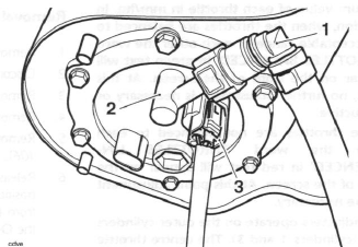
- Adaptor hose 'B'
- Fuel pump plate outlet
- Tool T3880123
8. Connect the fuel hose to the adaptor hose as shown in the illustration below.
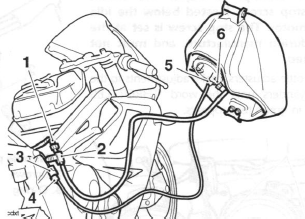
- Motorcycle fuel hose
- Adaptor hose 'B'
- Fuel pump connection
- Wiring extension T3880123
- Fuel pump connection
- Fuel pump plate outlet
9. Attach exhaust extraction hoses to the silencer.
10. Attach the Triumph diagnostic tool to the dedicated plug, refer to the Triumph Diagnostic Tool User Guide. Start the engine, and allow to idle.
11. On the diagnostic software navigate to 'ADJUST TUNE'.
12. Select 'BALANCE THROTTLES'.
13. Click the Adjust button.
Note:
- The balance throttle screen will show the vacuum value of each throttle in mm/hg. In addition, when the throttles are balanced to an acceptable range of each other the word 'THROTTLES BALANCED in green text will appear on the right of the screen. At this point, no further adjustment is necessary or productive.
- If the throttles are not balanced to each other the word 'THROTTLES UNBALENCED' in red text will appear on the right of the screen. At this point adjustment will be necessary.
- The adjusters operate on the outer cylinders only (cylinders 1 and 3). The centre throttle (cylinder 2) adjustment is fixed, this being controlled by the idle speed control stepper motor. Note that the centre reading will alter slightly as the two outer cylinders are adjusted.
- DO NOT attempt to adjust the centre throttle stop screw, located below the idle stepper motor. The stop screw is set at the factory during manufacture, and must not be adjusted.
14. Using the throttle adjusters, make adjustments to the two outer cylinders until the word 'THROTTLES BALANCED' in green text appears.
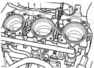
- Adjusters
15. When balanced, stop the engine and disconnect the diagnostic tool.
16. Disconnect the fuel pressure gauge adapter and wiring extension.
17. Refit the airbox.
18. Refit the fuel tank.
19. Remove the exhaust extraction hoses from the silencer.
20. Refit the rider's seat.
Throttle Position Sensor
Removal
1. Remove the rider's seat.
2. Disconnect the battery, negative (black) lead first.
3. Remove the fuel tank.
4. Remove the airbox.
5. Remove the throttle body assembly.
6. Release the two screws and rotate the throttle position sensor clockwise through 45º to remove it from the left hand end of the throttle body. Collect the O-ring on disassembly.
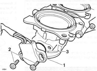
- Throttle position sensor
- Screws
- O-ring
Installation
1. Fit the replacement throttle position sensor ensuring the O-ring is positioned correctly between the sensor and throttle body. Rotate the sensor through 45º anti-clockwise until the screw holes align.
2. Engage the new screws and washers supplied and part tighten such that the sensor can still be rotated.
3. Position the throttle body assembly near to its fitted position and reconnect the sensor and all other throttle body electrical connectors.
4. Reconnect the battery, positive (red) lead first.
5. Attach the Triumph diagnostic tool to the dedicated plug, refer to the Triumph Diagnostic Tool User Guide.
6. Turn the ignition to the 'ON' position.
7. On the diagnostic software navigate to and select the 'ADJUST TUNE' option.
8. At the next screen, select Throttle Position Sensor Adjust then click the 'Adjust button.
9. On pressing the adjust button, the diagnostic tool will send a command, which drives the primary throttle to the fully closed position. The tool will also display the voltage reading coming from the throttle position sensor.
Gently rotate the new throttle position sensor until the voltage reading on the software shows 0.6 Volts +/- 0.02 Volts. The reading on the screen will turn green, indicating that the reading is correct.
Note:
- This is a setting voltage only. Because of the adaptive nature of the engine management system, the in-service voltage may vary from this setting figure.
10. Tighten the sensor retaining screws to 2 Nm and recheck the voltage reading shown on the tool.
Repeat the adjustment if the reading is outside the specified range.
11. Click on the OK button to return the throttle to normal control and return the diagnostic tool to the 'ADJUST TUNE' menu.
12. Disconnect the diagnostic tool.
13. Check that the throttle opens and closes without obstruction/sticking and has a smooth action throughout the full range of its movement. Rectify as necessary.
Warning: Operation of the motorcycle with an incorrectly adjusted throttle position sensor, or a throttle position sensor that causes the throttle to stick could result in loss of throttle control. Loss of throttle control could result in loss of control of the motorcycle and an accident.
Warning: Operation of the motorcycle with an incorrectly adjusted, incorrectly routed or damaged throttle cable could interfere with the operation of the brakes, clutch or the throttle itself. Any of these conditions could result in loss of control of the motorcycle a n d an accident.
14. Disconnect the battery, negative (black) lead first.
15. Refit the throttle body assembly.
16. Refit the airbox.
17. Refit the fuel tank.
18. Reconnect the battery, positive (red) lead first.
19. Check and clear any stored faults using the diagnostic tool, refer to the Triumph Diagnostic Tool User Guide.
20. Refit the rider's seat.
See also:
 Triumph Street Triple S - Service manual > Airbox
Removal 1. Remove the rider's seat. 2. Disconnect the battery, negative (black) lead first. 3. Remove the fuel tank. 4. Disconnect the ECM connectors.
 Triumph Street Triple S - Service manual > Idle Speed Control Stepper Motor
Removal 1. Remove the rider's seat. 2. Disconnect the battery, negative (black) lead first. 3. Remove the fuel tank. 4. Remove the airbox.

 Benelli Imperiale 400
 BMW F900XR
 Honda CB500X
 KTM 390 Adventure
 Triumph Street Triple S
 Yamaha MT-03
 Kawasaki Z400
 Triumph Street Triple S
 Yamaha MT-03