 Triumph Street Triple S - Service manual > Airbox
Removal
1. Remove the rider's seat.
2. Disconnect the battery, negative (black) lead first.
3. Remove the fuel tank.
4. Disconnect the ECM connectors.
5. Street Triple and Street Triple R only: Remove the three fixings and detach the relay and fuse box bracket. Without disconnecting any connectors, position the bracket assembly aside.
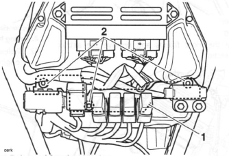
- Relay and fuse box bracket
- Fixings
6. All models: Disconnect the intake air temperature sensor multi-plug.
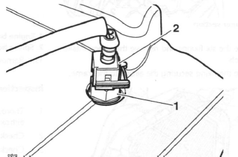
- Intake air temperature sensor
- Multi-plug
7. Disconnect the map sensor multi-plug.
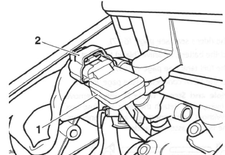
- Map sensor
- Multi-plug
8. Release the eight fixings and remove the airbox upper section.
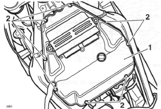
- Airbox upper section
- Fixings
9. Release the six fixings and remove the airbox intake trumpets.
10. Release the fixing securing the airbox to the frame.
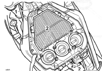
- Airbox front fixing location
- Airbox intake trumpet fixings
11. Release the spring hose clip and disconnect the secondary air injection hose at the airbox.
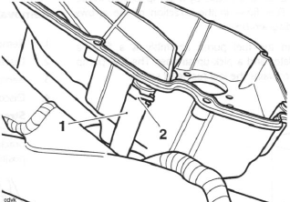
- Secondary air injection hose
- Spring hose clip
12. Release the spring hose clip and disconnect the engine breather hose at the airbox.
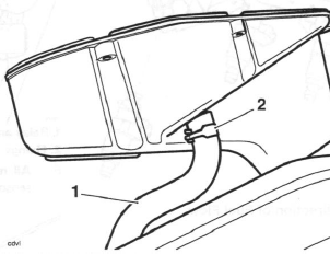
- Engine breather hose
- Spring hose clip
13. Remove the airbox from the motorcycle.
Inspection
1. Thoroughly clean the inside and outside of the airbox.
2. Check the airbox and intake trumpets for damage.
3. Check the air intake seal at the front of the airbox for damage.
Installation
1. Position the airbox to the frame.
2. Connect the engine breather hose and refit the spring hose clip.
3. Connect the secondary air injection hose and refit the spring hose clip.
4. Align the front of the air box to the frame and loosely install the fixing. Do not tighten the fixing at this stage.
5. Align the rear of the airbox to the throttle bodies and fit the airbox intake trumpets. Tighten the fixings to 6 Nm.
6. Tighten the airbox front fixing to 3 Nm.
7. Refit the airbox upper section and tighten the fixings to 1.5 Nm.
8. Reconnect the air temperature and map sensor multi-plugs.
9. Street Triple and Street Triple R only: Reposition the relay and fusebox bracket to the airbox and install the three fixings. Tighten the fixings to 3 Nm.
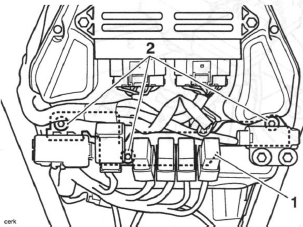
- Relay and fuse box bracket
- Fixings
10. All models: Reconnect the ECM connectors.
11. Refit the fuel tank.
12. Reconnect the battery, positive (red) lead first.
13. Refit the rider's seat.
Air Filter Element
Removal
Note:
- The air filter element can be accessed after first removing the airbox upper section. It is not necessary to remove the lower section.
1. Remove the rider's seat.
2. Disconnect the battery negative (black) lead first.
3. Remove the fuel tank.
4. Remove the airbox upper section.
5. Remove and discard the six fixings then remove the air filter element from the airbox lower section.
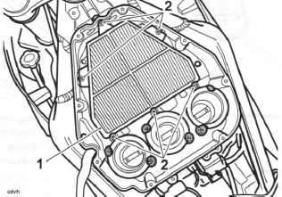
- Air filter element
- Fixings
Installation
1. Thoroughly clean the inside and outside of the airbox.
2. Seat the air filter element in the lower section.
3. Secure the air filter element with new fixings. Tighten to 4 Nm.
4. Refit the airbox upper section.
5. Refit the fuel tank.
6. Reconnect the battery, positive (red) lead first 7 Refit the rider's seat.
Intake Air Temperature Sensor
Removal
1. Remove the rider's seat.
2. Disconnect the battery, negative (black) lead first.
3. Remove the fuel tank.
4. Disconnect the intake air temperature sensor multi-plug.
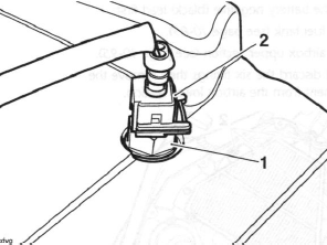
- Intake air temperature sensor (Daytona 675 shown)
- Multi-plug
Note:
- The intake air temperature sensor has a threaded base.
5. Unscrew the sensor to remove it from the airbox.
Installation
1. Fit the air temperature sensor to the airbox. Tighten the sensor to 4 Nm.
2. Reconnect the intake air temperature sensor multi-plug.
3. Refit the fuel tank.
4. Reconnect the battery, positive (red) lead first.
5. Refit the rider's seat.
Map Sensor
Removal
1. Remove the rider's seat.
2. Disconnect the battery, negative (black) lead first.
3. Remove the fuel tank.
4. Disconnect the map sensor multi-plug.
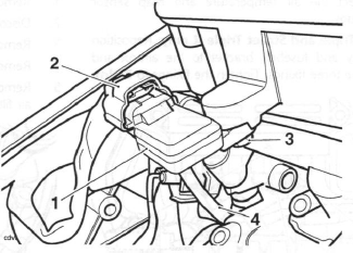
- Map sensor
- Multi-plug
- Fixing
- Vacuum hose
5. Disconnect the vacuum hose from the sensor.
6. Release the fixing screw securing the sensor to the airbox and remove the sensor.
Installation
1. Fit the sensor to the airbox, tightening the fixing to 3 Nm.
2. Refit the vacuum hose.
3. Reconnect the map sensor multi-plug.
4. Refit the fuel tank.
5. Reconnect the battery, positive (red) lead first.
6. Refit the rider's seat.
Barometric Pressure Sensor - Daytona 675 only
Removal
Note:
- The barometric pressure sensor is located on the intake air duct behind the fairing cockpit. It is not necessary to remove the cockpit to access the sensor.
1. Remove the rider's seat.
2. Disconnect the battery, negative (black) lead first.
3. Remove the windscreen.
4. Disconnect the multi-plug.
5. Release the fixing securing the sensor to the intake air duct and remove the sensor.
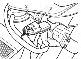
- Barometric pressure sensor (cockpit shown removed for clarity)
- Multi-plug
- Fixing
Installation
1. Fit the sensor to the intake air duct, tightening the fixing to 3 Nm.
2. Reconnect the multi-plug.
3. Refit the windscreen.
4. Reconnect the battery, positive (red) lead first.
5. Refit the rider's seat.
Barometric Pressure Sensor - Street Triple and Street Triple R only
Removal
Note:
- The barometric pressure sensor is located on the rear subframe, forward of the rear light unit.
1. Remove the rider's seat.
2. Disconnect the battery, negative (black) lead first.
3. Remove the rear bodywork.
4. Remove the rear light unit.
5. Disconnect the multi-plug.
6. Release the fixing securing the sensor to the rear subframe and remove the sensor.
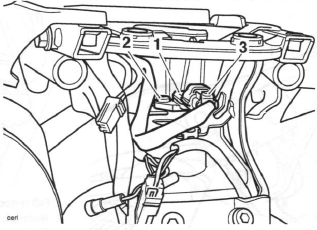
- Barometric pressure sensor
- Fixing
- Multi-plug
Installation
1. Fit the sensor to the rear subframe, tightening the fixing to 3 Nm.
2. Reconnect the multi-plug.
3. Refit the rear light unit.
4. Refit the rear bodywork.
5. Reconnect the battery, positive (red) lead first.
6. Refit the rider's seat.
Fall Detection Switch - Daytona 675 only
Removal
Note:
- The fall detection switch is located on the instrument bracket behind the fairing cockpit. It is not necessary to remove the cockpit to access the switch.
1. Remove the rider's seat.
2. Disconnect the battery, negative (black) lead first.
3. Remove the windscreen.
4. Disconnect the multi-plug.
5. Release the fixings securing the switch to the instrument bracket and remove the switch.
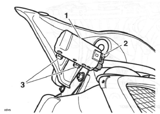
- Fall detection switch (cockpit shown removed for clarity)
- Multi-plug
- Fixings
Installation
1. Fit the switch to the instrument bracket, tightening the two fixings to 3 Nm.
2. Reconnect the multi-plug.
3. Refit the windscreen.
4. Reconnect the battery, positive (red) lead first.
5. Refit the rider's seat.
Fall Detection Switch - Street Triple and Street Triple R only
Removal
Note:
- The fall detection switch is located on the relay bracket fitted to the airbox.
1. Remove the rider's seat.
2. Disconnect the battery, negative (black) lead first.
3. Remove the fuel tank.
4. Disconnect the multi-plug.
5. Release the fixings securing the switch to the relay bracket and remove the switch.
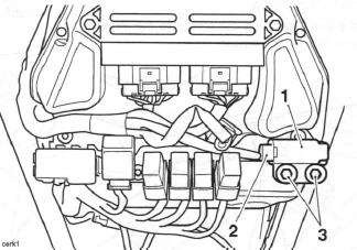
- Fall detection switch
- Multi-plug
- Fixings
Installation
1. Fit the switch to the relay bracket, tightening the two fixings to 3 Nm.
2. Reconnect the multi-plug.
3. Refit the fuel tank.
4. Reconnect the battery, positive (red) lead first.
5. Refit the rider's seat.
Intake Air Duct - Daytona 675 only
Removal
1. Remove the rider's seat.
2. Disconnect the battery, negative (black) lead first.
3. Remove the cockpit.
4. Remove the barometric pressure sensor.
5. Detach the instrument pack bracket, together with the fall sensor and its bracket and tie aside.
6. Disconnect the vacuum hose from the intake air flap actuator.
7 Release the four fixings securing the intake air duct to the frame headstock and remove the duct.
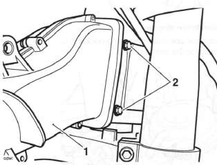
- Intake air duct
- Fixings (left hand shown)
Installation
1. Position the duct to the frame headstock and refit the four fixings. Tighten the fixings to 7 Nm.
2. Reconnect the intake air flap actuator vacuum hose.
3. Refit the instrument bracket and fall detection switch bracket.
4. Refit the barometric pressure sensor.
5. Refit the cockpit.
6. Reconnect the battery, positive (red) lead first.
7. Refit the rider's seat.
Intake Air Flap Actuator - Daytona 675 only
Operation
The intake air flap actuator is located on the intake air duct, forward of the instruments. It is vacuum operated, being controlled by a solenoid valve which is in turn operated by the ECM.
Removal
1. Remove the rider's seat.
2. Disconnect the battery, negative (black) lead first.
3. Remove the cockpit.
4. Remove the grille from the intake air duct.
5. Disconnect the vacuum hose from the intake air flap actuator.
6. Rotate the actuator one quarter turn clockwise to release it from the intake air duct.
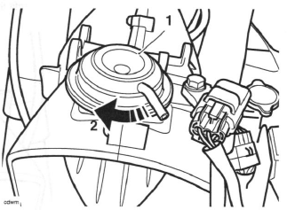
- Actuator
- Actuator release direction
7. Disconnect the actuator rod from the intake air flap and remove the actuator.
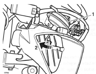
- Actuator
- Actuator rod removal direction
Installation
1. Position the actuator to the intake air duct and connect the actuator rod to the intake air flap.
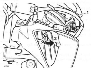
- Actuator
- Actuator rod installation direction
2. Rotate the actuator one quarter turn anti-clockwise to refit the actuator to the intake air duct.
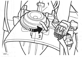
- Actuator
- Actuator installation direction
3. Reconnect the intake air flap actuator vacuum hose.
4. Refit the intake air duct grille.
5. Refit the cockpit.
6. Reconnect the battery, positive (red) lead first.
7. Refit the rider's seat.
Crankshaft position sensor
Note:
- The alternator stator and crankshaft position sensor are supplied as an assembly and cannot be separated.
See also:
 Triumph Street Triple S - Service manual > Fuel Tank
Removal Warning: Observe the warning advice given in the general information section on the safe handling of fuel and fuel containers. A fire, causing personal injury and damage to property, could result from spilled fuel or fuel not handled or stored correctly.
 Triumph Street Triple S - Service manual > Throttle Cable
Adjustment Note: Minor adjustments to the opening cable can be made using the adjuster near the throttle grip end of the throttle. Where a correct setting cannot be achieved this way, the adjusters at the throttle end of both cables must be used. The opening cable must be set first followed by the closing cable. Throttle grip Correct setting, 2-3 mm

 Benelli Imperiale 400
 BMW F900XR
 Honda CB500X
 KTM 390 Adventure
 Triumph Street Triple S
 Yamaha MT-03
 Kawasaki Z400
 Triumph Street Triple S
 Yamaha MT-03