 Triumph Street Triple S - Service manual > Idle Speed Control Stepper Motor
Removal
1. Remove the rider's seat.
2. Disconnect the battery, negative (black) lead first.
3. Remove the fuel tank.
4. Remove the airbox.
5. Remove the throttle bodies.
6. Remove the nut, metal washer and plastic washer attaching the idle control stepper arm to the idle speed control lever.
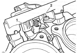
- Idle speed control lever
- Nut etc.
7. Remove the two screws securing the idle speed control stepper motor to its bracket, then remove the stepper motor in the direction shown.

- Idle speed control stepper motor
- Bracket
- Fixings
- Direction of removal
8. Leave the plastic collar and spring on the stepper motor arm.
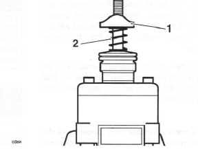
- Collar
- Spring
Installation
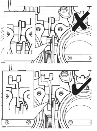
1. Ensure the Idle speed control lever is correctly positioned in relation to the throttle cam as shown below.
2. If removed, loosely fit the spring and collar on the stepper motor arm.
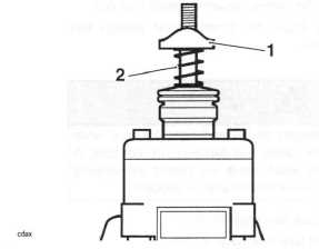
- Collar
- Spring
3. Locate the stepper motor to its bracket and tighten the fixings to 3.5 Nm.
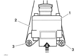
- Idle speed control stepper motor
- Bracket
- Fixings
- Direction of fitting
4. Fit the plastic washer to the lever then fit the metal washer and nut.
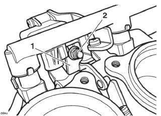
- Idle speed control lever
- Nut etc.
5. Mount the throttle body onto the engine.
6. Temporarily reconnect the battery, positive (red) lead first.
7. Attach the Triumph diagnostic tool to the dedicated plug, refer to the Triumph Diagnostic Tool User Guide.
8. Turn the ignition to the 'ON' position.
9. On the diagnostic software navigate to and select the 'ADJUST TUNE' option.
10. Select Idle Speed Control Stepper Motor Adjust then click the Adjust button.
11. On pressing the adjust key, the diagnostic tool will send a command that drives the throttle to the fully closed position. The tool will also display the voltage reading coming from the throttle position sensor which should be between the target voltage range of 0.58V and 0.62V 12. Tighten the stepper arm nut on the idle speed stepper motor until a clearance of 0.5 mm can be measured between the idle speed control cam and the throttle roller.
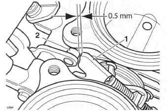
- Idle speed control lever
- Throttle roller
13. Check the voltage reading shown on the software. If the reading is between the target voltage range, then proceed to step 17. If the reading is not within this range, adjustment must be made as described in steps 14 to 16.
14. Slacken the screws on the throttle position sensor.
15. Gently turn the throttle position sensor until the voltage reading shown on the software is between the target voltage range.
16. Tighten the sensor retaining screws to 2 Nm and recheck the voltage reading shown on the software.
Repeat the adjustment if the reading is outside the specified range.
17. Click the OK button to progress to the next adjustment.
Note:
- The diagnostic software will calculate the target voltage range for when the throttle is in the fully open position.
18. On pressing the OK button, the diagnostic tool will send a command that drives the throttle to the fully open position. The tool will also display the voltage reading coming from the throttle position sensor which should be between the target voltage range calculated by the software and shown on the screen.
19. With the stepper fully opened, check the voltage shown on the software and, if necessary, adjust the nut on the top of the stepper arm until the software shows a voltage within the target voltage range shown on the screen. The reading on the screen will change from red to green, indicating that the reading is correct.
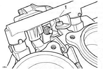
- Adjustment nut
20. Click the OK button to fully close the idle speed control stepper motor. After a minimum of 15 seconds (the tool will show 'Adapting and not allow further actions to take place during this period), click the OK button again to return the ECM to normal control.
Caution: Do not operate the throttle while the stepper motor is being adjusted, otherwise the incorrect value will be adapted and the engine will not start.
21. Turn the ignition to the 'OFF' position.
22. Disconnect the diagnostic tool.
23. Disconnect the battery, negative (black) lead first.
24. Check and adjust the throttle cable settings.
Warning: Move the handlebars to left and right full lock while checking that the cables and harnesses do not bind. A cable or harness which binds will restrict the steering and may cause loss of control and an accident.
25. Refit the airbox.
26. Refit the fuel tank.
27. Reconnect the battery, positive (red) lead first.
28. Refit the rider's seat.
Engine Management Adaption
General Information
The engine management system fitted to the Daytona 675, Street Triple and Street Triple R is adaptive.
This means that the system is able to learn about new or changing operating conditions and continuously adapt itself without needing to constantly make major adjustments from a fixed baseline setting.
Adaptive changes can become necessary because of changing rider behaviour, changes in the region in which the bike is operated (i.e. operation at high altitude where it was previously used at sea level) or because a new part may have been fitted which has slightly different characteristics to the old part. All adaptive changes are automatic and require no intervention by rider or dealer.
Adaption Status
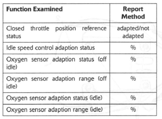
To see if a motorcycle has fully adapted, a facility named 'ADAPTION STATUS' is provided on the diagnostic software. The following adaption details can be examined:
Terminology
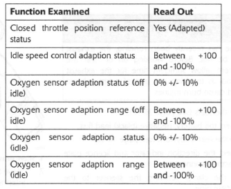
Where the term 'status' is used, this indicates how far the present operating parameter is from the stored (baseline) value. The nearer these figures are to zero the better as it indicates the motorcycle has adapted to its current operating conditions.
The term 'range' indicates how much (in percentage terms) of the adjustment range has been used to reach the current operating status.
Typical Values
In a correctly adapted motorcycle, the following will be typical:
Forcing adaption to take place
If the read out indicates that the motorcycle is not adapted, the following will force the system to make adaptions:
1. Ensure the engine is cold.
2. WITHOUT TOUCHING THE THROTTLE, start the engine and allow it to warm up until the cooling fan comes on.
3. Leave the engine to idle for a further 12 minutes.
Note:
- As an alternative to the above process, connect the diagnostic tool, select ADJUST TUNE (see the Triumph Diagnostic Tool User Guide) and select RESET ADAPTIONS. This will force a fast adaption routine to take place in around 5 seconds. For this to happen, the engine MUST be running, it must be at normal operating temperature and in closed loop control mode. Under any other conditions fast adaption will not take place and may cause default values to be loaded, which may then require a normal 12 minute adaption routine to be run.
Fault Indications
If 'range' figures at 100% are seen, then the adjustment has reached maximum indicating a mechanical fault exists on the motorcycle. This can be due to a number of faults but the most likely causes will be low/high fuel pressure, faulty injectors or air leaks at the throttle bodies or airbox.
In these circumstances, locate and rectify the fault, and reset the adaptions as described above.
See also:
 Triumph Street Triple S - Service manual > Throttle Cable
Adjustment Note: Minor adjustments to the opening cable can be made using the adjuster near the throttle grip end of the throttle. Where a correct setting cannot be achieved this way, the adjusters at the throttle end of both cables must be used. The opening cable must be set first followed by the closing cable. Throttle grip Correct setting, 2-3 mm
 Triumph Street Triple S - Service manual > Exhaust System - Daytona 675
Removal Warning: If the engine has recently been running, the exhaust system will be hot. Before working on or near the exhaust system, allow sufficient time for the exhaust system to cool as touching any part of a hot exhaust system could cause burn injuries.

 Benelli Imperiale 400
 BMW F900XR
 Honda CB500X
 KTM 390 Adventure
 Triumph Street Triple S
 Yamaha MT-03
 Kawasaki Z400
 Triumph Street Triple S
 Yamaha MT-03