 Triumph Street Triple S - Service manual > Pistons
Disassembly
Note:
- It is not necessary to remove the connecting rods from the crankshaft.
1. Remove the cylinder head.
2. Remove the liner, using the frame from tool T3880315, and tool T3880101.
3. Remove and discard the gudgeon pin circlip from one side of the piston.
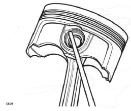
Removing the Gudgeon Pin Circlip
4. Remove the gudgeon pin by pushing the pin through the piston and rod toward the side from which the circlip was removed.
Caution: Never force the gudgeon pin through the piston. This may cause damage to the piston which may also damage the liner when assembled.
Note:
- If the gudgeon pin is found to be tight in the piston, check the piston for a witness mark caused by the circlip. Carefully remove the mark to allow the pin to be removed.
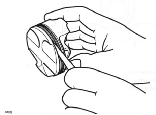
5. Piston rings must be removed from the piston using hand pressure only. Do not over-extend the piston rings during removal.
Note:
- If the piston rings are to be re-used, note the orientation of the oil control rings prior to removal.
Piston Wear Check
1. Measure the piston outside diameter, 8 mm up from the bottom of the piston and at 90º to the direction of the gudgeon pin.
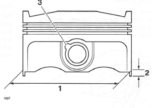
- Piston outside diameter
- Measurement point
- Circlip removal groove
Daytona 675
All Cylinders: 73.970 - 73.980 mm
Service limit: 73.920 mm
Street Triple and Street Triple R
All Cylinders: 73.964 - 73.980 mm
Service limit: 73.920 mm
Replace the piston if the measured diameter falls outside the specified limit.
Piston Rings/Ring Grooves
Check the pistons for uneven groove wear by visually inspecting the ring grooves.
If all the rings do not fit parallel to the groove upper and lower surfaces, the piston must be replaced.
Clean the piston ring grooves.
Fit the piston rings to the pistons. Check, using feeler gauges, for the correct clearance between the ring grooves and the rings. Replace the piston and rings if outside the specified limit.
Piston Ring to Ring Groove Clearance Check
Piston ring/Groove Clearance
Top ring: 0.040 - 0.080 mm
Service limit: 0.095 mm
Second: 0.020 - 0.060 mm
Service limit: 0.075 mm
Piston Ring Gap
Note:
- The piston ring gap, with the piston ring fitted in the liner, must be checked before final assembly.
1. Place the piston ring inside the liner.
2. Push the ring into the top of the cylinder, using the piston to hold the ring square with the inside of the bore. Continue to push the ring into the bore until the third groove of the piston is level with the cylinder top, around the full circumference of cylinder.
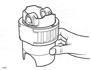
Aligning Piston Rings using the Piston
1. Remove the piston and measure the gap between the ends of the piston ring using feeler gauges.
Piston Ring End Gap Tolerances
Top: 0.10 - 0.25 mm
Service limit: 0.37 mm
Second: 0.25 - 0.40 mm
Service limit: 0.52 mm
Oil Control: 0.10 - 0.35 mm
Service limit: 0.49 mm
Note:
- If the end gap is too large, replace the piston rings with a new set
- If the gap remains too large with the new piston rings, both the pistons and barrels must be replaced
- If the gap is too small, check the cylinder bore for
distortion, replacing as necessary.
Do not file piston rings!
Piston Assembly
1. Clean the piston ring grooves and fit the piston rings to the piston.
Note:
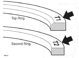
- The top ring upper surface is marked 'T1' and can be identified by a chamfer on the inside edge. When new, the top ring also has a blue paint marking on its outer edge.
- The second ring upper surface is marked 'T2', is plain on the inside edge and has a bronze appearance. When new, the second ring also has a yellow paint marking on its outer edge.
- When new, the oil control rings can be fitted with either face upward. Used oil control rings must be refitted in the same orientation as noted prior to removal. When new, the oil control rings have white paint markings on their outside edge.
Piston Ring Identification
- Fit the piston onto the connecting rod.
Note:
- Connecting rods may be fitted either way around. However, ensure all three are fitted the same way.
2. Lubricate the piston, small end and gudgeon pin with a 50/50 solution of engine oil and molybdenum disulphide grease.
3. Align the small end in the connecting rod with the gudgeon pin hole in the piston and fit the gudgeon pin.
4. Fit new circlips on both sides of the gudgeon pin ensuring the circlips are correctly fitted in the grooves.
Warning: Failure to use new gudgeon pin circlips could allow the pin to detach from the piston. This could seize the engine and lead to an accident.
5. The piston ring gaps must be arranged as shown in the diagram below.
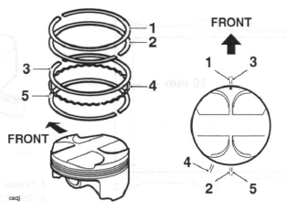
- Top ring
- Second ring
- First steel oil control ring
- Oil control ring expander
- Second steel oil control ring
Note:
- The top ring gap should be positioned in the 12 o'clock position, and the second ring gap in the 6 o'clock position. The first steel oil control ring gap should be in the 12 o'clock position and the second steel oil control ring should be in the 6 o'clock position. The oil control ring expander should be in the 7 o'clock position.
6. Fit the piston into the liner from below using a gentle rocking motion to engage the rings in the bore.
Cylinder Wear
Measure the inside diameter of each cylinder using an internal micrometer or similar accurate measuring equipment.
Cylinder bore diameter
Standard: 73.985 - 74.003 mm
Service limit: 74.100 mm
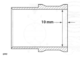
Test Position For Bore Wear Check (bore shown in section)
1. Measure the inside diameter 10 mm from the top of the bore as shown above.
2. If the reading is outside the specified limits, replace the liner and piston as an assembly.
Cylinder Liners
Removal
1. Assemble the frame from tool T3880315 to Tool T3880315 as shown below.
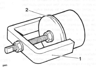
- Frame from tool T3880315
- Tool T3880101
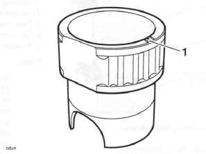
- Paint mark
2. Mark each liner to identify correct orientation and the cylinder number from which it has been removed.
3. Turn the crankshaft until the piston in the liner to be removed is at the bottom of its stroke.
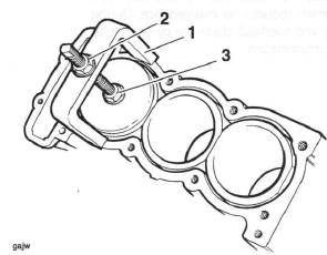
- Tool T3880315 and T3880101
- Extraction nut
- Locking nut
4. Check that the locking nut on tool T3880101 is loose, then fully unscrew the extraction nut.
5. Carefully fit the tool fully into the cylinder bore, positioning the tool legs on the crankcase. Turn the locking nut clockwise until the rubber sleeve on the tool tightly grips the bore of the liner.
6. Check that the tool legs are positioned to allow withdrawal of the liner, then turn the extraction nut clockwise to extract the liner. Take care to ensure that the piston/connecting rod is not allowed to fall against the inside of the crankcase.
7. Turn the locking nut counter-clockwise to release the liner.
Note:
- The tool must be used to release the seal between the liner and the crankcase.
- It is not intended that the tool is used to fully extract the liner. Once the seal is released, the tool must be removed and the liner extracted by hand.
Installation
1. Thoroughly clean the liner removing all traces of old silicone sealer.
2. Remove all traces of sealer from the crankcase bores.
3. Apply silicone sealer to the liner to crankcase mating face (at the factory, ThreeBond 1215 is used).
4. Fit each liner over the piston using a gentle rocking motion to allow compression of the piston rings.
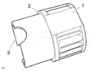
- Liner
- Sealer area
- Chamfer
Note:
- The liners have a large chamfer at the bottom of the bore enabling fitting of the piston without need for a piston ring compressor.
Caution: Fit each liner over whichever piston is at TDC. When turning the engine, do not allow the pistons to contact the inside of the crankcase and also do not allow fitted liners to lift off the crankcase base.
5. Continue fitting each liner in turn until all are fitted and sealed.
Note:
- When the liners have been fitted, they should not be disturbed. If it is necessary to remove the liner after fitting, the sealer must be re-applied.
Crankcase Breather
The upper crankcase is fitted with a labyrinth type breather system, which requires no maintenance. During engine disassembly and overhaul, check the oil drain tube for blockage and contamination.
See also:
 Triumph Street Triple S - Service manual > Connecting Rods
Removal Connecting rods may be removed from the engine after first removing it from the frame. The cylinder head must be removed and the crankcase halves separated.
Triumph Street Triple S - Service manual > Balancer
Exploded View - Balancer Shaft Balancer
 Benelli Imperiale 400
 BMW F900XR
 Honda CB500X
 KTM 390 Adventure
 Triumph Street Triple S
 Yamaha MT-03
 Kawasaki Z400
 Triumph Street Triple S
 Yamaha MT-03