 Triumph Street Triple S - Service manual > Connecting Rods
Removal
Connecting rods may be removed from the engine after first removing it from the frame. The cylinder head must be removed and the crankcase halves separated.
1. Mark each big end cap and connecting rod to identify both items as a matched pair and to identify the correct orientation of the bearing cap to the connecting rod.
2. Release the connecting rod bolts and remove the big end cap. Ensure that the bearing shell remains in place in the cap.
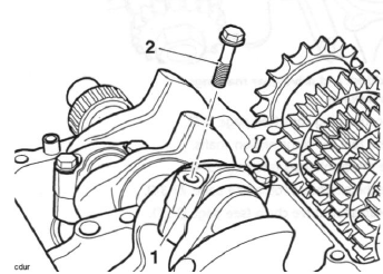
- Big end cap
- Connecting rod bolt
Note:
- It may be necessary to gently tap the big end cap with a rubber mallet to release the cap.
3. Push the connecting rod up through the crankcase and collect the piston and connecting rod from the top.
4. Label the assembly to identify the cylinder from which it was removed.
Caution: Never re-use connecting rod bolts. If the connecting rod cap is disturbed, always renew the bolts. Using the original bolts may lead to severe engine damage.
5. Remove the liner using tool T3880101.
6. Detach the piston from the connecting rod.
Installation
Note:
- Connecting rod bolts are treated with an anti-rust solution which must not be removed.
- Clean the connecting rod with high flash - point solvent.
- Remove all bearings and inspect for damage, wear and any signs of deterioration and replace as necessary.
Warning: Connecting rod bolts MUST only be used once. If the bolts are removed or undone for any reason, new bolts MUST always be used.
Re-using bolts can cause connecting rods and their caps to detach from the crankshaft causing severe engine damage, loss of motorcycle control and an accident.
Note:
- Ensure the piston is fitted correctly to the connecting rod.
- If a previously run engine is being rebuilt, always ensure that the piston and con-rod are assembled in the same orientation, and to the same cylinder, as prior to strip-down.
1. Fit the piston onto the connecting rod.
2. Apply silicone sealer to the liner-to-crankcase mating face (At the factory, Three Bond 1215 is used).
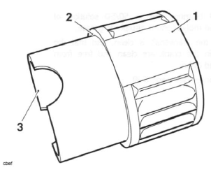
- Liner
- Sealer area
3. Fit the piston and connecting rod assembly into the liner from the bottom.
4. Fit the liner into the crankcase ensuring that the arrow/'dot' on the piston faces forward.
5. The liners must be positioned such they do not touch each other - it must be possible to pass a 0.1 mm feeler gauge between the centre liner and its adjacent liner on either side. If the liners touch at any point, rotate the liners until there is a minimum 0.1 mm clearance.
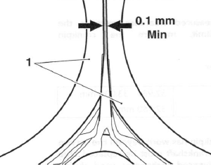
- Liners
Note:
- Ensure that the piston/liner/connecting rod assembly aligns correctly with the crankpin during assembly into the crankcase.
6. Select the big end bearing shells.
7. Fit the bearing shells to the connecting rod and big end cap and lubricate with a 50/50 solution of engine oil and molybdenum disulphide grease.
8. Align the connecting rod to the crankshaft and fit the big end cap.
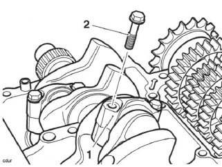
- Big end cap
- Connecting rod bolt
Caution The torque characteristics of the connecting rod bolts are sensitive to the correct lubrication being applied. If the threads and under head areas are not lubricated with molydenum disuplhide grease, the bolts may be stretched and may become loose when in service resulting in an expensive engine failure.
9. Lubricate the threads and under-head area of the new bolts with molybdenum disulphide grease.
Tighten the bolts evenly and progressively in five stages as follows:
Caution: The torque characteristics of the connecting rod bolts are sensitive to the rate at which they are tightened. If all the torque is applied in one action, the bolt may be stretched and may become loose when in service resulting in an expensive engine failure.
- Tighten to 22 Nm
- Release 120º
- Tighten to 10 Nm
- Tighten to 14 Nm
- Tighten through 120º of bolt rotation as measured using the Triumph torque turn gauge 3880105- T0301.
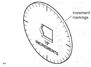
Service Tool 3880105-T0301
Connecting Rod Big End Bearing Selection/Crankpin Wear Check
1. Measure the bearing and crankpin clearance as follows.
Note:
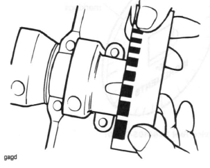
- The crankpin clearances are measured using 'Plastigage' (Triumph part number 3880150 - T0301).
- Do not turn the connecting rod and crankshaft during the clearance measurement as this will damage the 'Plastigage'.
- Remove the big end cap from the journal to be checked.
- Wipe the exposed areas of the crankpin, and the bearing face inside the cap.
- Apply a thin smear of grease to the journal and a small quantity of silicone release agent to the bearing.
- Trim a length of the Plastigage to fit across the journal. Fit the strip to the journal using the grease to hold the Plastigage in place.
- Lubricate the threads and under-head of the bolt with molybdenum disulphide grease. Refit the bearing and cap and tighten the big end bolts.
- Release the bolts and remove the cap being measured. Using the gauge provided with the Plastigage kit, measure the width of the compressed Plastigage.
Checking the Measured Clearance
Con rod big end bearing/crankpin clearance
Standard: 0.035 - 0.065 mm
Service limit: 0.070 mm
Note:
- If the measured clearance exceeds the service limit, measure the crankpin diameter.
Crankpin diameter
Standard: 32.984 - 33.000 mm
Service limit: 32.960 mm
Note:
- If any crankpin has worn beyond the service limit, the crankshaft must be replaced. Due to the advanced techniques used during manufacture, the crankshaft cannot be reground and no oversize bearings are available.
Connecting Rod Bearing Selection
Minor differences in crankshaft dimensions are compensated for by using selective bearings. For further information on bearing part number to colour cross-references, see the latest parts information.
1. Select the correct big end bearing shell as follows:
- Measure each crankpin diameter.
- Select the correct bearings by matching the information found with the chart below.
Note:
- All dimensions in millimetres.
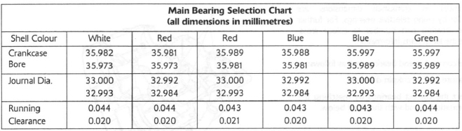
Big end bearing selection chart
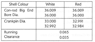
For instance:
Con-rod Big End Diameter - 36.002
Crankpin Diameter - 32.987
Required Bearing - Red
Note:
- Repeat the measurements for all connecting rods and their respective crankpins.
- It is normal for the bearings selected to differ from one connecting rod to another.
2. Install the new bearings in the connecting rod.
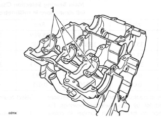
- Big end bearings
Caution: Always confirm, using the Plastigage method, that the running clearance is correct before final assembly.
Severe engine damage could result from incorrect clearance.
Crankshaft main bearing/journal wear
Minor differences in crankshaft and crankcase dimensions are compensated for by using selective bearings. For further information on bearing part number to colour cross-references, see the latest parts information.
- Measure the bearing to crankshaft main journal clearance using Plastigage (Triumph part number 3880150-T0301).
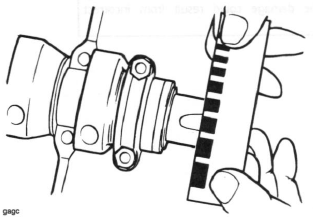
Checking Crankpin Clearance using Plastigage
Crankshaft main bearing/journal clearance
Standard: 0.020 - 0.044 mm
Service limit: 0.07 mm
If the clearance exceeds the service limit, measure the diameter of the crankshaft main journal.
Crankshaft main journal diameter
Standard: 32.984 - 33.000 mm
Service limit: 32.960 mm
Note:
- If any journal has worn beyond the service limit, the crankshaft must be replaced. Due to the techniques used during manufacture, the crankshaft cannot be reground and no oversize bearings are available.
Select bearings as follows:
1. Measure and record the diameter of each crankshaft main bearing journal.
2. Measure and record each main bearing bore diameter in the crankcase (bearings removed).
Compare the data found with the chart above to select bearings individually by journal.
For example:
Crankshaft Journal diameter - 32.995 mm
Crankcase Bore - 35.997 mm
Bearing Required - Blue
Note:
- It is normal for the bearings selected to differ from one journal to another.
- It is also normal for there to be two options of bearing shell colour. In such cases, pick the shell size which gives the greater running clearance.
Caution: Always confirm, using the Plastigage method, that the running clearance is correct before final assembly.
Severe engine damage could result from incorrect clearance.
Crankshaft End Float
Standard: 0.15 - 0.30 mm
Note:
- Crankshaft end float is controlled by the tolerances in crankshaft and crankcase machining. No thrust washers are used. If the crankshaft end float is outside the specified limit, the crankshaft and/or the crankcases must be replaced.
See also:
 Triumph Street Triple S - Service manual > Crankcases
Caution: The upper and lower crankcases are machined as a matched set and must never be assembled to non-matching halves. Doing so may cause seizure of the engine. 1. Remove the engine from the frame.
Triumph Street Triple S - Service manual > Pistons
Disassembly Note: It is not necessary to remove the connecting rods from the crankshaft.
 Benelli Imperiale 400
 BMW F900XR
 Honda CB500X
 KTM 390 Adventure
 Triumph Street Triple S
 Yamaha MT-03
 Kawasaki Z400
 Triumph Street Triple S
 Yamaha MT-03