 Triumph Street Triple S - Service manual > Balancer
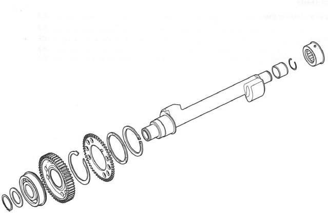
Exploded View - Balancer Shaft
Balancer
The balancer is fitted to control 'pulsing within the engine.
Without any form of balancer, the engine would 'pulse' each time the crankshaft rotated. This 'pulsing' would be felt as a vibration which would amplify as the engine speed was increased.
The balancer has the effect of a pair of counterbalance weights which create an equal amount of energy in the opposite direction, and at the same time as that produced by the crankshaft, pistons and connecting rods. Because the opposing pulses occur at the same point of crankshaft rotation, and are of an equal magnitude, a state of equilibrium or balance is reached.
Removal
1. Separate the crankcase halves.
2. With the crankcase halves separated, lift out the balancer shaft complete with the shaft bearings/ circlips.
Note:
- As the shaft is released from the crankcase, the backlash eliminator gear will spring out of alignment with the crankshaft.
3. To remove the left hand bearing, slide the bearing, circlip and bearing sleeve from the balancer shaft.
Note the orientation of the bearing prior to removal.
4. To remove the right hand bearing, remove the circlip and washer, and, using a press and press bars remove the bearing race from the shaft, ensuring the inner bearing race is supported. Note the orientation of the bearing prior to removal. DO NOT remove the drive gear from the shaft.
Warning: When using a press, always wear overalls, eye face and hand protection. Objects such as bearings frequently break-up under load and the debris caused during break-up may cause damage and injury to unprotected parts of the body.
Never wear loose clothing, which could become trapped in the press and cause crushing injury to the hand, arms or other parts of the anatomy.
Caution: Do not remove the drive gear from the balancer shaft.
The drive gear is aligned to the shaft. If the balancer and drive gear are not correctly aligned, severe engine vibration will occur leading to damage to components.
5. To strip the backlash eliminator from the drive gear, release the circlip and remove the wave-washer, backlash gear and spring.
- Balancer shaft
- Wave washer
- Circlip
Inspection
1. Inspect all gears for chipped or missing teeth.
2. Inspect all bearings for signs of overheating (blue discolouration), seized or damaged rollers, and any other damage.
3. Inspect the backlash spring for deformities, damage etc.
4. Inspect the gear teeth for overheating (blue discolouration).
Assembly/ Installation
Note:
- Before assembling the backlash gear to the balancer shaft, lubricate all contact surfaces of the balancer drive gear, backlash spring and backlash gear with a 50/50 solution of engine oil and molybdenum disulphide grease.
1. If the backlash gear was disassembled, fit the backlash spring over the shaft and position to the balancer drive gear, positioning the spring ends on either side of the peg.
2. Fit the backlash gear, ensuring its peg is located anticlockwise (viewed from the left hand bearing end of the shaft) of the balancer gear peg and also between the spring ends.
- Balancer shaft
- Backlash gear
- Backlash spring
3. Fit the wave washer and secure all components in position with the circlip.
- Balancer shaft
- Wave washer
- Circlip
4. Using a press and press bars, fit the right hand bearing to the shaft, with the circlip positioned nearest to the drive gear. Ensure the inner race of the bearing is supported when installing the bearing.
Warning: When using a press, always wear overalls, eye face and hand protection. Objects such as bearings frequently break-up under load and the debris caused during break-up may cause damage and injury to unprotected parts of the body.
Never wear loose clothing, which could become trapped in the press and cause crushing injury to the hand, arms or other parts of the anatomy.
5. Refit the washer and a new circlip to the shaft.
6. Lubricate and fit the left hand bearing and install a new circlip in the same orientation as noted prior to removal.
Note:
- Prior to installation in the crankcase, it is essential that
the markings on the backlash eliminator and drive gears are brought into
alignment against the tension of the spring.
This will facilitate correct positioning of the balancer in relation to the crankshaft when both are installed in the crankcase.
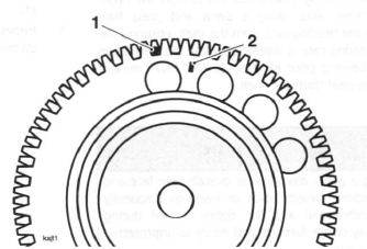
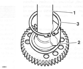
- Drive gear 'dot'
- Backlash gear line
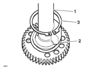
7. Using tool T3880106, bring the backlash and drive gear marks into alignment against the backlash spring as follows:
- Engage the peg of tool T3880106 into a tooth of the backlash gear. Rotate the backlash gear against the spring until the marks align.
Note:
- When in alignment, the line on the backlash gear must be located directly above the drive gear tooth marked with a 'dot'.
- Since the drive gear 'dot' cannot be seen when the backlash gear is in alignment, always mark the 'dot'-marked gear tooth with a paint mark in order that it can always be identified.
8. Secure the backlash gear in position with the fixture supplied with the tool by placing the fixture pegs across two gear teeth (ensure that the fixture will not be in the way when assembling the balancer to the crank).
- Tool T3880106
- Securing fixture
- Balancer backlash gear marking
Caution: If the balancer and crankshaft are not correctly aligned, severe engine vibration will occur leading to damage to components.
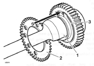
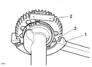
9. With the drive and backlash eliminator gears still correctly aligned, locate the balancer to the crankcase. Align the balancer gears and crankshaft as shown in the illustration below.

- Balancer gear marking
- Crankshaft markings
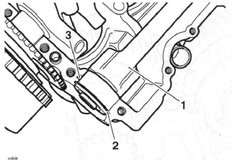
10. Ensure that the right hand bearing circlip and dowel locate correctly in the corresponding groove in the crankcase.
- Balancer shaft (right hand bearing)
- Circlip
- Dowel
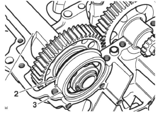
11. Ensure that the left hand bearing circlip and dowel locate correctly in the corresponding groove in the crankcase
- Balancer shaft (left hand bearing)
- Circlip
- Dowel
12. Remove the securing fixture.
13. Check that the balancer and crankshaft are correctly aligned before continuing to assemble the crankcase halves.
14. Assemble the crankcase halves.
See also:
 Triumph Street Triple S - Service manual > Pistons
Disassembly Note: It is not necessary to remove the connecting rods from the crankshaft.
Triumph Street Triple S - Service manual > Transmission
Exploded View, Input and Output Shafts - up to Engine Number 330118
 Benelli Imperiale 400
 BMW F900XR
 Honda CB500X
 KTM 390 Adventure
 Triumph Street Triple S
 Yamaha MT-03
 Kawasaki Z400
 Triumph Street Triple S
 Yamaha MT-03