 Triumph Street Triple S - Service manual > Output Shaft
Note:
- The numbers in brackets in the following text refer to the exploded view.
Working from the opposite end to the drive sprocket, dismantle the output shaft as follows.
Disassembly
1. Remove the output shaft bearing (1) and plain thrust washer (2).
2. Mark one side of first gear to denote its correct orientation. Remove first gear (3) from the shaft, complete with the plain bush (4) which runs inside the gear.
3. Remove the plain thrust washer (5).
4. Mark one side of fifth gear to denote its correct orientation. Remove fifth gear (6) from the shaft.
5. Remove the circlip (7) and splined thrust washer (8) from in front of fourth gear.
6. Mark one side of fourth gear to denote its correct orientation. Remove fourth gear (9) complete with the splined bush which runs inside the gear (10).
7. Remove the splined lock washers (11 and 12).
8. Mark one side of third gear to denote its correct orientation. Remove third gear (14) off the shaft complete with the splined bush (13) which runs inside the gear.
9. Remove the splined thrust washer (15).
10. Remove the circlip (16) from in front of sixth gear.
11. Mark one side of sixth gear to denote its correct orientation. Remove sixth gear (17) from the shaft.
12. Remove the circlip (18) from in front of second gear.
13. Remove the splined thrust washer (19).
14. Mark one side of second gear to denote its correct orientation. Remove second gear (21) from the shaft, complete with the plain bush (20) which runs inside the gear.
15. Position the output shaft (22) in a vice with soft jaws fitted. Tighten the vice to prevent the shaft from turning and release the tab washer (28) from the output sprocket nut (29), then release the nut.
16. Remove the output sprocket nut (29), tab washer (28) and sprocket (27).
17. Collect the output shaft seal (26).
18. If it is found necessary to replace the large bearing (24) at the end of the shaft, use a press to remove both the bearing and output shaft sprocket spacer (25) together.
Warning: When removing the output shaft bearing, always wear overalls, eye, face and hand protection. The bearing races are hardened and are liable to splinter if broken.
Debris from broken bearings could cause injury to eyes, face and any unprotected parts of the body.
Exploded View - Output Shaft
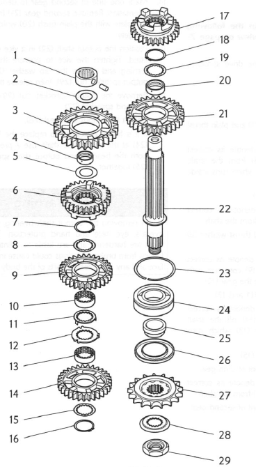
- Bearing
- Thrust washer
- First gear
- Plain bush
- Thrust washer
- Fifth gear
- Circlip
- Splined thrust washer
- Fourth gear
- Splined bush
- Lock washer
- Splined washer
- Splined bush
- Third gear
- Splined washer
- Circlip
- Sixth gear
- Circlip
- Splined thrust washer
- Plain bush
- Second gear
- Output shaft
- Snap ring
- Bearing
- Sprocket spacer
- Output shaft seal
- Output sprocket
- Tab washer
- Output sprocket nut
Assembly
Note:
- The numbers in brackets in the following text refer to the exploded view.
- Lubricate each gear and bush with clean engine oil during assembly.
- Examine all gears, bearings and sleeves for damage, chipped teeth and wear beyond the service limits. Replace all suspect components and always use new circlips, a new output shaft seal and a new sprocket tab washer to assemble the shaft.
Warning: When using a press, always wear overalls, eye face and hand protection. Objects such as bearings frequently break-up under load and the debris caused during break-up may cause damage and injury to unprotected parts of the body.
Never wear loose clothing, which could become trapped in the press and cause crushing injuries to the hand, arms or other parts of the anatomy.
Caution: Bushes and gears with oil holes must always be MISALIGNED with the corresponding oil holes in the output shaft. Reduced oil pressure and gear lubrication may result from alignment of the oil holes, which would cause premature wear of engine and transmission components.
Caution: Removing the output shaft bearing from the shaft will damage the bearing and snap ring. Never re-use removed bearings or snap rings as use of damaged or weakened components could lead to engine and transmission damage.
Caution: Press only on the bearing inner race to prevent bearing damage.
1. Working from the output sprocket end of the shaft, fit a new bearing (24) and a new sprocket spacer (25) to the shaft using a press and press bars. Fit the sleeve with the large chamfer facing outwards.
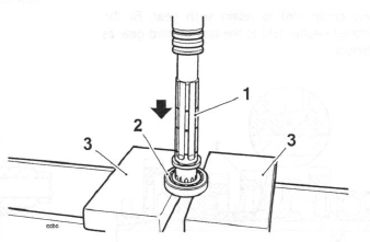
- Output shaft
- Bearing
- Press bars
2. Lubricate and fit a new output shaft seal (26).
3. Transfer the shaft to the vice and secure between soft jaws. Fit the output sprocket (27), new tab washer (28) and nut (29). Tighten the nut to 85 Nm. Close the tab washer.
4. Withdraw the shaft from the vice and continue to assemble from the opposite end to the output sprocket.
5. Fit the plain bush (20) to the shaft.
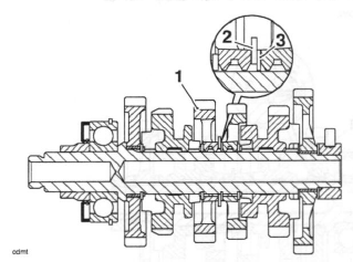
6. Locate second gear (21) to the shaft as noted during disassembly, with the large step side facing towards the output sprocket end. Fit the splined thrust washer (19) and retain with a new circlip (18) as shown below.
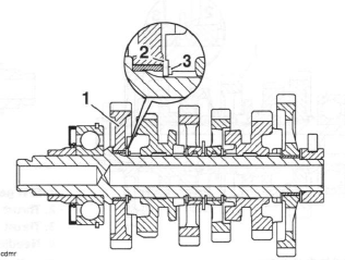
- Second gear
- Thrust washer
- Circlip
7. Fit sixth gear (17) as noted during disassembly, with the selector fork groove facing away from the output sprocket end. Ensure that the oil holes in the gear DO NOT align with the corresponding oil hole in the output shaft.
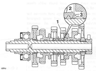
8. Fit a new circlip (16) to retain sixth gear. Fit the splined thrust washer (15) to the rear of third gear as shown below.
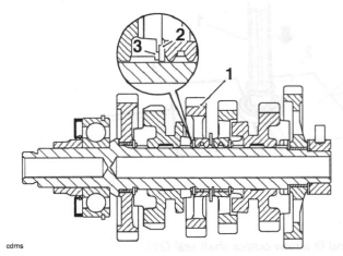
- Third gear
- Splined thrust washer
- Circlip
9. Fit the splined bush (13) for third gear. Ensure that the oil holes in the gear DO NOT align with the corresponding oil hole in the output shaft. Fit third gear (14) to the shaft with the large step side facing away from the output sprocket.
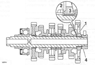
10. Fit the splined lock washers (12 and 11), ensuring the tabs in the smaller washer (11) locate in the slots in the larger washer (12) as shown below.
- Third gear
- Large splined lock washer
- Small splined lock washer
11. Fit the splined bush (10) from fourth gear. Ensure that the oil holes in the gear DO NOT align with the corresponding oil hole in the output shaft.
12. Fit fourth gear (9) as noted during disassembly, with the larger step side facing towards the output sprocket.
13. Fit the splined thrust washer (8) and retain with a new circlip (7) as shown below.
- Fourth gear
- Splined thrust washer
- Circlip
14. Fit the fifth gear (6) to the shaft with the groove facing towards the output sprocket. Ensure that the oil holes in the gear DO NOT align with the corresponding oil hole in the output shaft.
15. Fit the first gear thrust washer (5) and plain bush (4).
16. Fit first gear (3) to the shaft as marked during disassembly as shown below.
- First gear
- Thrust washer
- Thrust washer
- Needle roller bearing
17. Finally fit the thrust washer (2) and needle roller bearing (1) to the end of the shaft.
See also:
 Triumph Street Triple S - Service manual > Input Shaft
Disassembly Note: The numbers in brackets in the following text refer to the exploded view.
Triumph Street Triple S - Service manual > Starter Drive Gears/Sprag Clutch
Removal Note: The sprag clutch may be detached after first removing the rider's seat and the battery (disconnect the negative (black) lead first). The left hand lower fairing (Daytona 675 only) and the alternator must also be removed. Refer to the relevant sections for removal procedures.
 Benelli Imperiale 400
 BMW F900XR
 Honda CB500X
 KTM 390 Adventure
 Triumph Street Triple S
 Yamaha MT-03
 Kawasaki Z400
 Triumph Street Triple S
 Yamaha MT-03