 Triumph Street Triple S - Service manual > Input Shaft
Disassembly
Note:
- The numbers in brackets in the following text refer to the exploded view.
Working from the opposite end to where the clutch assembly is fitted, dismantle the input shaft as follows:
1. Slide off the plain thrust washer (1).
2. Mark one side of second gear to denote its correct orientation. Remove second gear (2).
3. Remove the splined lock washers (3 and 4).
4. Mark one side of sixth gear to denote its correct orientation. Remove sixth gear (6), complete with the splined bush (5) which runs inside the gear.
5. Remove the splined thrust washer (7) from in front of the circlip between sixth and third/fourth gear.
6. Remove the circlip (8) from the shaft.
7. Mark one side of the combined third/fourth gear to denote its correct orientation. Remove the combined third/fourth gear (9).
8. Remove the circlip (10) from in front of fifth gear.
9. Remove the splined thrust washer (11) adjacent to fifth gear.
10. Mark one side of fifth gear to denote its correct orientation. Remove fifth gear (12), complete with the plain bush (13) which runs inside the gear.
Note:
- Unless the bearing at the clutch end of the input shaft is damaged or worn, it is not normally necessary to remove it from the shaft. The bearing is pressed onto the shaft and is also pressed into its housing. The bearing and housing are removed from the shaft together and are then separated.
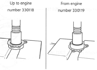
- Up to engine number 330118, the bearing is retained in the bearing housing with a circlip.
11. Up to engine 330118 only: Remove the circlip (15) from the bearing housing.
Warning: When using a press, always wear overalls, eye face and hand protection. Objects such as bearings frequently break-up under load and the debris caused during break-up may cause damage and injury to unprotected parts of the body.
Never wear loose clothing, which could become trapped in the press and cause crushing injuries to the hand, arms or other parts of the anatomy.
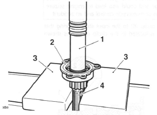
12. Support the bearing and housing (16 and 17) on press bars, then press the shaft (14) through the bearing and housing as shown below.
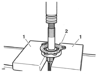
- Press bars
- Bearing/housing
13. All engines: Support the outer circumference of the bearing housing on press bars, then press the bearing through the housing.
Pressing out the Bearing
Inspection
1. Examine all gears, bearings and bushes and thrust washers for damage, distortion, chipped teeth and wear beyond the service limits. Replace all defective components and always use new circlips to assemble the shaft.
2. Thoroughly clean the bearing housing and inspect for damage, scoring and cracks. Replace the housing if necessary.
Exploded View - Input Shaft
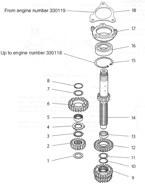
- Thrust washer
- Second gear
- Lock washer
- Splined washer
- Splined bush
- Sixth gear
- Splined thrust washer
- Circlip
- Third/fourth gear
- Circlip
- Splined thrust washer
- Fifth gear
- Plain bush
- Input shaft
- Circlip
- Bearing
- Bearing housing
- Bearing retainer
Assembly
Note:
- The numbers in brackets in the following text refer to the exploded view.
- Lubricate each gear, thrust washer and bush with clean engine oil during assembly.
Warning: When using a press, always wear overalls, eye face and hand protection. Objects such as bearings frequently break-up under load and the debris caused during break-up may cause damage and injury to unprotected parts of the body.
Never wear loose clothing, which could become trapped in the press and cause crushing injuries to the hand, arms or other parts of the anatomy.
Caution: Bushes and gears with oil holes must always be MISALIGNED with the corresponding oil holes in the input shaft. Reduced oil pressure and gear lubrication may result from alignment of the oil holes, which would cause premature wear of engine and transmission components.
Caution: Removing the input shaft bearing from the shaft and its housing will damage the bearing and snap ring. Never re-use removed bearings or snap rings as use of damaged or weakened components could lead to engine and transmission damage. Also, check for damage to the housing itself.
1. Up to engine number 330118 only: Apply approximately 1 gram of ThreeBond 1375B to the circumference of a new bearing and position the bearing to the housing, ensuring the bearing dowel aligns with the slot in the housing. Ensure no ThreeBond enters the bearing.
Caution: Press only on the bearing outer race to prevent bearing damage.
2. Support the housing on press bars as shown below and press the bearing fully into the housing in the direction of the arrow.
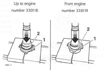
- Bearing housing
- Bearing
3. Up to engine number 330118 only: Retain the bearing with a new circlip.
Caution: Press only on the bearing inner race to prevent bearing damage.
4. Locate the bearing and housing to the input shaft.
Carefully support the shaft on the press bed, and using a suitable sleeve over the input shaft to ensure the bearing is pressed only on the inner race, press the bearing onto the shaft.
- Sleeve
- Bearing/housing
- Press bars
- Input shaft
5. Fit the plain bush (13) to the shaft.
6. Fit fifth gear (12) to the input shaft as noted during disassembly, with the dog teeth pointing away from the input shaft bearing.
7. Slide on the splined thrust washer (11).
8. Fit a new circlip (10) to the input shaft ensuring that the clip is located in the circlip groove as shown below.
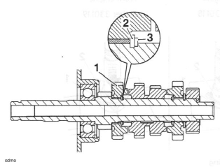
- Fifth gear
- Thrust washer
- Circlip
9. Fit the combined third/fourth gear (9) as noted during disassembly, with the larger gear facing toward fifth gear. Ensure that the oil hole in the input shaft DOES NOT align with the oil hole in the gear.
Warning: If the oil hole in the third/fourth gear is aligned with the corresponding hole in the input shaft, engine oil pressure and gear lubrication will be reduced.
Reduced oil pressure and gear lubrication will cause engine damage and could also lead to engine seizure resulting in loss of motorcycle control and an accident.
10. Fit a new circlip (8) to the input shaft ensuring that the circlip is located in the circlip groove as shown below.
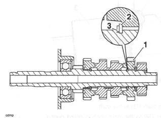
- Sixth gear
- Thrust washer
- Circlip
11. Fit the splined thrust washer (7) to the input shaft and slide up the shaft until in contact with the circlip.
12. Fit the splined bush (5) from sixth gear. Ensure that the oil hole in the input shaft DOES NOT align with the oil hole in the gear.
13. Fit sixth gear (6) as noted during disassembly, with the dog teeth facing third/fourth gear.
14. Fit the splined and lock washers (4 and 3), ensuring the tabs in the smaller washer (3) locate in the slots in the larger (4) washer.
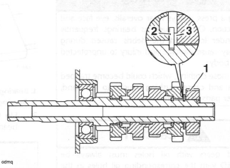
- Second gear
- Large splined lock washer
- Small splined lock washer
15. Fit second gear (2) to the shaft as noted during disassembly.
16. Fit the plain thrust washer (1) adjacent to second gear.
See also:
 Triumph Street Triple S - Service manual > Input and Output Shafts Assemblies
Removal Note: The input and output shafts may be removed from the upper crankcase after first separating the lower crankcase from the upper.
Triumph Street Triple S - Service manual > Output Shaft
Note: The numbers in brackets in the following text refer to the exploded view. Working from the opposite end to the drive sprocket, dismantle the output shaft as follows.
 Benelli Imperiale 400
 BMW F900XR
 Honda CB500X
 KTM 390 Adventure
 Triumph Street Triple S
 Yamaha MT-03
 Kawasaki Z400
 Triumph Street Triple S
 Yamaha MT-03