 Triumph Street Triple S - Service manual > Lubrication
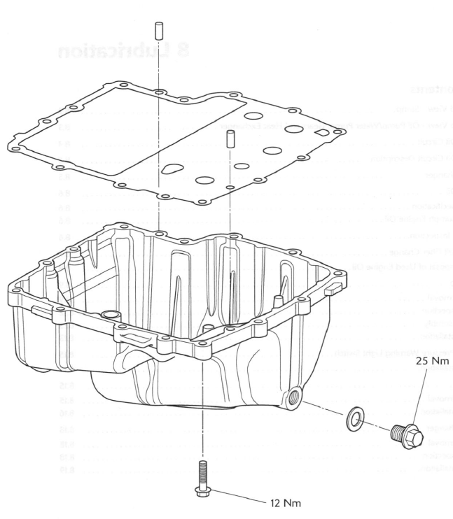
Exploded View - Sump
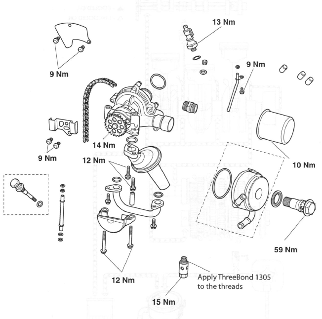
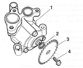
Exploded View - Oil Pump/Water Pump, Gears and Heat Exchanger
Engine Oil Circuit
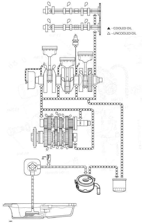
Engine Oil Circuit Description
Oil is collected from the sump and is drawn through a mesh strainer into the oil pump rotor. The oil pump is fitted with a single pumping rotor which supplies pressurised oil to the lubrication circuit via the oil pressure relief valve. The relief valve is set to open at 5.1 bar (75 Ib/in 2) and when open, returns high pressure oil direct to the sump.
Pressurised oil is delivered to the oil to water heat exchanger (mounted on the front of the engine), where it is cooled.
The cooled oil is then delivered to the outside rim of the oil filter, where it is filtered by passing through the filter membrane. Filtered oil is then fed into the lower crankcase gallery. From here it is distributed around the engine:
- Oil is delivered to the crankshaft main bearings and, via drillings in the crankshaft, to the big end bearings.
- Spray lets located in the upper crankcase, behind the main bearing shells, lubricate the pistons and connecting rod small ends. These jets are fed oil from the crankshaft oil feed. A low oil pressure warning light switch is also located in the upper crankcase gallery.
- Some oil is sent directly to the cylinder head via an internal gallery. Oil that arrives at the cylinder head is fed to both cams via a gallery in the cylinder head casting that delivers oil directly to the sprocket end of the camshafts. Oil is then fed through the hollow camshafts to the other camshaft bearings, the tappet buckets and the valves.
- Oil is fed to the gearbox via internal oil pipes and drillings that supply oil directly to the end of each shaft. Oil is circulated along the gearbox shafts to exit holes that feed directly to the bearings, gears and selectors.
On the Daytona 675, Street Triple and Street Triple R, oil is also fed to the alternator to aid cooling of the alternator components. The oil is taken from the crankshaft oil feed and directed to the alternator via a jet, located above the alternator rotor, in the upper crankcase.
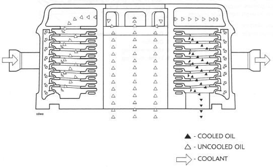
Heat Exchanger
The heat exchanger is used to transfer heat from the engine oil into the coolant. Oil is delivered to the heat exchanger via a hollow centre bolt, after which it flows around the end tank and into the heat exchanger core, where it is circulated.
Coolant is pumped around the outside of the heat exchanger core to cool the oil. The cooled oil then exits the heat exchanger and flows to the oil filter. An additional benefit of the heat exchanger is that, as the engine coolant reaches its operating temperature more quickly than the engine oil, the oil is heated by the engine coolant at lower engine temperatures; this allows the engine oil to reach its optimum operating temperature more quickly, thereby helping to improve engine oil life, reduce exhaust emissions and reduce engine wear.
Heat Exchanger Circuit
Engine Oil
Specification
Use semi or fully synthetic 10W/40 or 15W/50 motorcycle engine oil which meets specification API SH (or higher) and JASO MA, such as Mobil 1 Racing 4T.
Caution: Triumph high performance fuel injected engines are designed to use semi or fully synthetic motorcycle engine oil which meets specification API SH (or higher) AND JASO MA.
Do not add any chemical additives to the engine oil. The engine oil also lubricates the clutch and any additives could cause the clutch to slip.
Do not use mineral, vegetable, non-detergent oil, castor based oils or any oil not conforming to the required specification. The use of these oils may cause instant, severe engine damage.
Ensure no foreign matter enters the crankcase during an oil change or top-up.
Triumph Engine Oil
Your Triumph Motorcycle is a quality engineered product which has been carefully built and tested to exacting standards. Triumph Motorcycles are keen to ensure that you enjoy optimum performance from your machine and with this objective in mind have tested many of the engine lubricants currently available to the limits of their performance.
Mobil 1 Racing 4T consistently performed well during our tests and has become our primary recommendation for the lubrication of all current Triumph motorcycle engines.
Mobil 1 Racing 4T, specially filled for Triumph, is available from your authorised Triumph dealer.
Oil Level Inspection
In order for the engine, transmission, and clutch to function correctly, maintain the engine oil at the correct level, and change the oil and oil filter in accordance with scheduled maintenance requirements.
Warning: Motorcycle operation with insufficient, deteriorated, or contaminated engine oil will cause accelerated engine wear and may result in engine or transmission seizure.
Seizure of the engine or transmission may lead to loss of motorcycle control and an accident.
1. Start the engine and run at idle for approximately five minutes.
2. Stop the engine, then wait for at least three minutes to allow the oil to settle.
3. Remove the dipstick, wipe clean and screw fully home in the crankcase.
- Filler
- Dipstick location in crankcase
- Dipstick
- Upper marking
- Lower marking
Note:
- The actual level is indicated when the motorcycle is level and upright, not on the side stand, and when the filler has been screwed fully home.
- Do not add oil through the dipstick hole in the crankcase.
4. Remove the dipstick.
5. The oil level is indicated by lines on the dipstick.
When full, the indicated oil level must be level with the upper marking on the dipstick.
6. If the oil level is too low, remove the filler plug and add oil a little at a time through the filler plug hole in the clutch cover, until the correct level is reached.
7. Once the correct level is reached, fit the dipstick and the filler plug.
Oil and Oil Filter Change
Warning: Prolonged or repeated contact with engine oil can lead to skin dryness, irritation and dermatitis. In addition, used engine oil contains potentially harmful contamination which can cause cancer. Wear suitable clothing and avoid skin contact.
The engine oil and filter must be replaced in accordance with scheduled maintenance requirements.
1. Warm up the engine thoroughly, and then stop the engine.
2. Daytona 675 only: Remove the lower fairings.
3. Place an oil pan beneath the engine.
Warning: The oil may be hot to the touch. Contact with hot oil may cause the skin to be scalded or burned.
4. Remove the oil drain plug.
- Oil drain plug
- Oil filter
5. With the motorcycle on level ground, and on the sidestand, allow the oil to completely drain.
6. Unscrew and remove the oil filter using Triumph service tool T3880313.
- Oil filter
- Tool T3880313
7. Discard the oil filter.
8. Apply a smear of clean engine oil to the sealing ring of the new oil filter.
9. Fit the oil filter and tighten to 10 Nm using Triumph service tool T3880313.
10. After the oil has completely drained out, fit a new sealing washer to the drain plug. Fit and tighten the plug to 25 Nm.
11. Fill the engine with new oil of the type and grade listed previously and in the specification section.
12. Start the engine and allow to idle.
Caution: Racing the engine before the oil reaches every part can cause engine damage or seizure.
13. Ensure that the oil pressure warning light extinguishes shortly after starting.
Caution: If the engine oil pressure is too low, the low oil pressure warning light will illuminate. If this light stays on when the engine is running, stop the engine immediately and investigate the cause. Running the engine with low oil pressure will cause engine damage.
14. Stop the engine and check the oil level. Adjust if necessary.
15. Daytona 675 only: Refit the lower fairings.
Disposal of Used Engine Oil
To protect the environment, do not pour oil on the ground, down sewers or drains, or into water courses.
Dispose of used oil sensibly. If in doubt contact your local authority.
Oil Pump
Warning: Prolonged or repeated contact with engine oil can lead to skin dryness, irritation and dermatitis. Furthermore, used engine oil contains potentially harmful contaminants which can cause cancer.
When handling used engine oil, always wear protective clothing and avoid any skin contact with the oil.
Caution: Do not pour engine oil on the ground, down sewers or drains, or into water courses. To prevent pollution of water courses etc., dispose of used oil sensibly. If in doubt contact your local authority.
Removal
Note:
- The oil pump and water pump are supplied as an assembly and
cannot be separated.
This procedure covers the removal of the oil and water pump assembly.
1. Remove the rider's seat.
2. Disconnect the battery, negative (black) lead first.
3. Drain the coolant.
4. Drain the engine oil.
Warning: The oil may be hot to the touch. Contact with hot oil may cause the skin to be scalded or burned.
Warning: Prolonged or repeated contact with engine oil can lead to skin dryness, irritation and dermatitis. In addition used engine oil contains potentially harmful contaminants which can cause cancer. Wear suitable clothing and avoid skin contact.
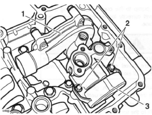
5. Remove the sump.
6. Remove the clutch.
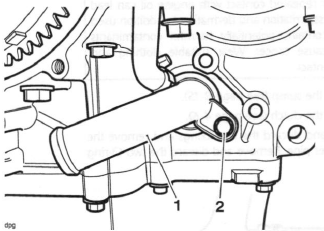
7. Release and discard the two fixings and remove the oil transfer pipe. Remove and discard the two O-ring seals.
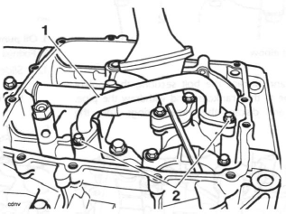
- Oil transfer pipe
- Fixings
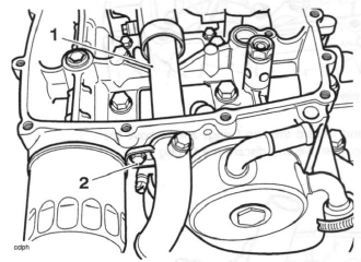
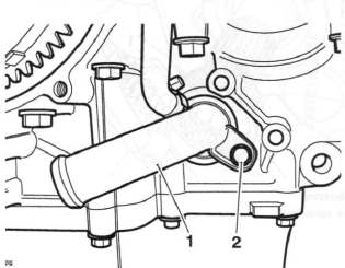
8. Release and discard the two fixings and remove the oil pick-up. Remove and discard the O-ring seal.
- Oil pick-up
- Fixings
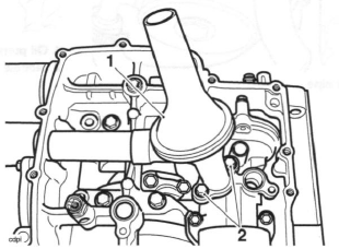
9. Remove and discard the bolt securing the coolant inlet elbow to the crankcase and withdraw the elbow.
Remove and discard the O-ring from the elbow.
- Coolant inlet elbow
- Fixing
10. Remove and discard the bolt securing the coolant outlet pipe to the crankcase and withdraw the pipe.
Remove and discard the three O-rings from the pipe.
- Coolant outlet pipe
- Fixing
11. Release the fixings securing the drive chain guide to the crankcase and remove the guide.
- Oil pump drive chain guide
- Fixings
12. Slide the oil pump drive sprocket gently backwards and forwards to dislodge the inner needle roller bearing.
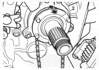
- Oil pump drive sprocket
- Needle roller bearing
13. Carefully remove the bearing while supporting the oil pump drive sprocket.
- Needle roller bearing
- Oil pump drive sprocket
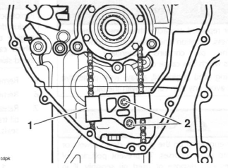
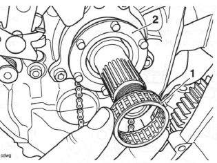
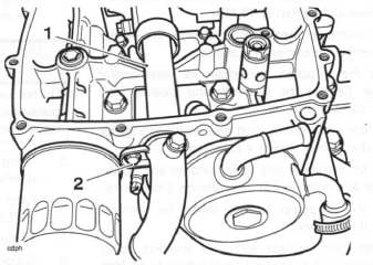
14. Release the fixings securing the drive chain cover to the oil pump. Remove the drive chain cover.
- Oil pump
- Fixings
- Drive chain cover
15. Using a suitable tool, slide the dowel upwards to release the oil pump from the crankcase. It is not necessary to remove the dowel completely from the oil pump.
- Oil pump
- Dowel
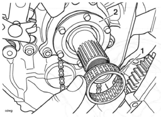
16. Detach the drive chain from the oil pump.
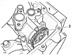
- Oil pump
- Drive chain
17. Carefully withdraw the oil pump from the crankcase.
18. Remove and discard the O-ring from the inlet sleeve on the water pump body.
Inspection
1. Release the fixing and remove the drive sprocket and spacer washer.
- Oil pump
- Spacer washer
- Drive sprocket
- Fixing
2. Release the three fixings and withdraw the oil pump body.
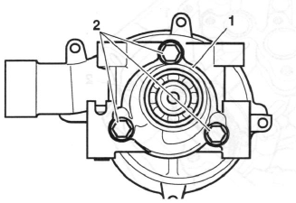
- Oil pump body
- Fixings
Caution: If any part of the oil pump is found to be outside the service limit, the complete pump must be replaced.
Severe engine damage may result from the continued use of a faulty oil pump.
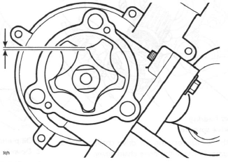
3. Measure the rotor tip clearance using feeler gauges.
Rotor Tip Clearance
Standard: 0.15 mm
Service limit: 0.20 mm
Rotor Tip Clearance
4. Measure the pump body clearance using feeler gauges.
Pump Body Clearance
Pump Body Clearance
Standard: 0.15 - 0.22 mm
Service limit: 0.35 mm
5. Measure the pump end clearance.
Pump End Clearance
Standard: 0.04 - 0.09 mm
Service limit: 0.17 mm
Assembly
1. If all clearances are within service limits, liberally apply clean engine oil to all internal components and refit the oil pump body to the oil pump rotor. Refit the fixings and tighten to 12 Nm.
2. If any clearance measured is outside the service limits, renew the complete pump.
3. Inspect the sprockets and chain for wear and/or damage. Replace the sprockets and chain if wear and/or damage is found.
4. Check the water pump shaft and shaft bearings for side and end float. Renew if necessary.
5. Check for corrosion and scale build-up around the impeller and in the pump body. Renew if necessary.
6. Check the oil pump location dowel for damage.
Renew if necessary.
7. Refit the spacer washer and drive sprocket. Apply ThreeBond 1374 to the fixing and tighten to 14 Nm.
- Oil pump
- Spacer washer
- Drive sprocket
- Fixing
Installation
Caution: Before fitting the oil pump to the crankcase ensure the pump internal surfaces have been 'wetted' with clean engine oil. The pump may fail to pick-up oil from the sump if the surfaces have not been 'wetted'. This will cause the engine to run without engine oil pressure and will lead to severe engine damage.
1. Install a new O-ring to the inlet sleeve on the water pump body.
2. Fill the oil pump with new engine oil, turning the pump rotor as the oil is poured in to ensure all surfaces are coated with oil.
3. Position the oil pump to the crankcase and insert the water pump inlet sleeve into the opening in the crankcase.
4. Fit the oil pump to the crankcase, ensuring the oil pump dowel correctly locates into the bolt hole in the crankcase.
Caution: Do not use excessive force to insert the dowel into the crankcase. Severe dowel or crankcase damage may result from the use of excessive force.
5. Using a suitable pin punch, gently tap the dowel downwards into the crankcase until it seats.
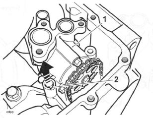
6. Feed the drive chain over the transmission input shaft and fit to the sprocket.
7. Fit the drive chain to the sprocket on the oil pump.
8. Support the oil pump drive sprocket and carefully refit the needle roller bearing.
- Needle roller bearing
- Oil pump drive sprocket
9. Refit the oil pump drive chain cover to the oil pump and fit new bolts. Tighten the bolts to 12 Nm.
- Oil pump
- Fixings
- Drive chain cover
10. Refit the oil pump drive chain guide. Install new fixings and tighten to 9 Nm.
11. Install a new O-ring to the coolant inlet elbow and position the elbow to the water pump inlet. Fit a new bolt and tighten to 9 Nm.
- Coolant inlet elbow
- Fixing
12. Install three new O-rings to the coolant outlet pipe and position the pipe through the crankcase, locating it to the water pump outlet. Install a new fixing and tighten to 9 Nm.
- Coolant outlet pipe
- Fixing
13. Install a new O-ring to the oil pick-up and refit the oil pick-up. Fit new bolts and tighten to 12 Nm.
14. Install two new O-rings to the oil transfer pipe and refit the oil transfer pipe. Fit new bolts and tighten to 12 Nm.
15. Refit the clutch.
16. Refit the sump, ensuring the water pump drain tube is correctly installed.
17. Reconnect the battery, positive (red lead) first.
18. Refit the rider's seat.
19. Refill the engine with oil.
20. Refill the cooling system.
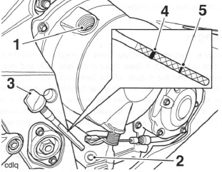
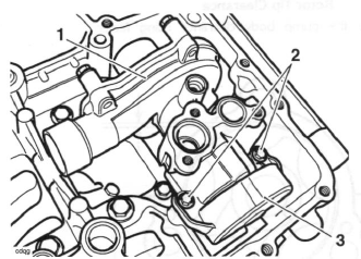
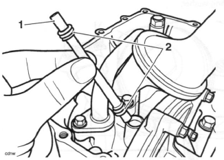
Low Oil Pressure Warning Light Switch
The low oil pressure warning light switch is located in the upper crankcase, behind the cylinder head.
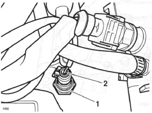
- Low oil pressure warning light switch
- Electrical connection
1. Remove the rider's seat.
2. Disconnect the battery, negative (black) lead first.
3. Disconnect the electrical connection to the switch.
4. Remove the switch and collect the copper washer.
Installation
1. Incorporating a new copper washer, fit the switch and tighten to 13 Nm.
2. Refit the electrical connection.
3. Reconnect the battery, positive (red) lead first.
4. Refit the rider's seat.
Sump
Removal
1. Remove the rider's seat.
2. Disconnect the battery, negative (black) lead first.
3. Drain the engine oil.
Warning: The oil may be hot to the touch. Contact with hot oil may cause the skin to be scalded or burned.
Warning: Prolonged or repeated contact with engine oil can lead to skin dryness, irritation and dermatitis. In addition used engine oil contains potentially harmful contaminants which can cause cancer. Wear suitable clothing and avoid skin contact.
4. Remove the exhaust system.
Warning: The exhaust system will be hot if the engine has recently been running. Always allow sufficient time for the exhaust to cool before working on or near the exhaust system.
Contact with a hot exhaust could result in burn injuries.
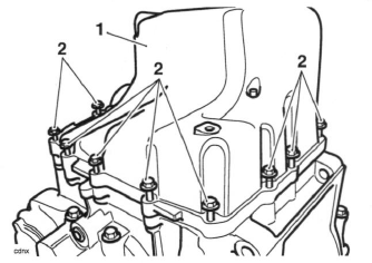
5. Release the bolts securing the sump to the lower crankcase.
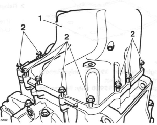
- Sump
- Fixings
6. Detach the sump and collect the water pump drain tube. Remove and discard the four drain tube O-rings.
Note:
- The water pump drain tube may remain attached to the water pump or become detached with the sump.
- Water pump drain tube
- O-rings
Note:
- From engine number 395930 a new sump gasket/baffle was introduced and is retrofitable.
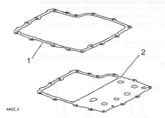
- Gasket
- Gasket/baffle
7. Up to engine number 395929 only: Remove and discard the sump gasket.
From engine number 395930 only: Remove the sump gasket/baffle.
8. If necessary, release and discard the oil transfer pipe fixings and remove the oil transfer pipe. Remove and discard the two O-rings from the crankcase.
- Oil transfer pipe
- Fixings
Installation
- Oil transfer pipe
- Fixings
1. If removed, fit the oil transfer pipe incorporating new O-rings. Fit new fixings and tighten to 12 Nm.
2. Incorporating new O-rings, position the water pump drain tube to the oil pump.
- Water pump drain tube
- O-rings
3. Up to engine number 395929 only: Incorporating a new sump gasket/baffle, position the sump to the lower crankcase.
From engine number 395929 only: Check the sump gasket/baffle for wear or damage, replace if necessary. Position the sump to the lower crankcase.
4. Tighten the sump fixings to 12 Nm.
- Sump
- Fixings
5. Refit the exhaust system.
6. Fill the engine with the correct grade of engine oil.
7. Reconnect the battery, positive (red) lead first.
8. Start the engine and ensure that the low oil pressure warning light goes out shortly after starting.
9. Stop the engine and check the engine oil level.
Adjust if necessary.
10. Daytona 675 only: Refit the lower fairings.
11. Refit the rider's seat.
Heat Exchanger
Removal
Note:
- Prior to disassembly of the coolant hoses, note the orientation and position of the hose clips to help ensure that they are returned to the same positions and orientation on assembly.
1. Position the motorcycle on level ground on the sidestand.
2. Remove the rider's seat.
3. Disconnect the battery, negative (black) lead first.
4. Daytona 675 only: Remove the lower fairings.
5. Drain the coolant.
6. Drain the engine oil.
Warning: The oil may be hot to the touch. Contact with hot engine oil may cause skin to be scalded or burnt.
Warning: Prolonged or repeated contact with engine oil can lead to skin dryness, irritation and dermatitis. In addition used engine oil contains potentially harmful contaminants which can cause cancer. Wear suitable clothing and avoid skin contact.
7. Disconnect the coolant hoses from the heat exchanger.
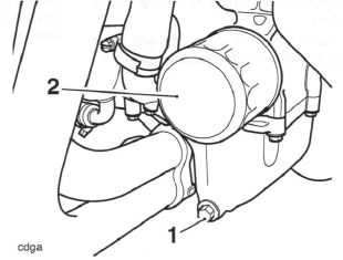
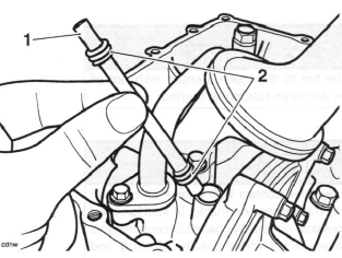
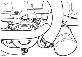
8. Remove the centre bolt from the heat exchanger and withdraw it from the crankcase. Remove and discard the heat exchanger O-ring and the centre bolt sealing washer.
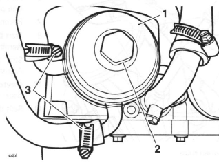
- Heat exchanger
- Centre bolt
- Coolant hose clips
Inspection
1. Check the heat exchanger body for corrosion and/or damage.
Installation
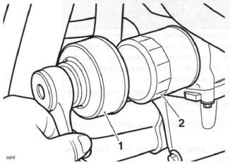
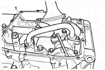
1. Fit a new O-ring to the heat exchanger, and a new sealing washer to the centre bolt.
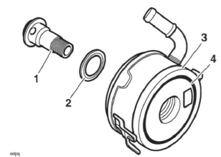
- Centre bolt
- Sealing washer
- Heat exchanger
- O-ring
Note:
- To ensure correct positioning, ensure that the tab on the heat exchanger locates in the boss provided in the crankcase.
Caution: Do not rely on the tab to hold the heat exchanger in position while tightening the centre bolt. The tab will bend and will not prevent the heat exchanger from turning. Instead, firmly hold the heat exchanger in position by hand.
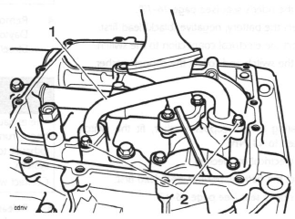
- Heat exchanger tab
- Crankcase boss
2. Fit the heat exchanger to the crankcase and tighten the centre bolt to 59 Nm.
3. Fit the coolant hoses to the heat exchanger and tighten the coolant hose clips.
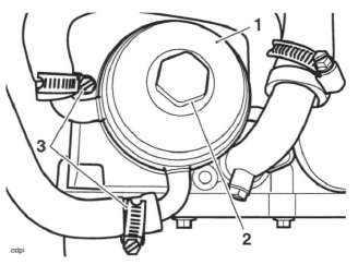
- Heat exchanger
- Centre bolt
- Coolant hoses
4. Refill the cooling system.
5. Refill the engine with oil.
6. Daytona 675 only: Refit the lower fairings.
7. Reconnect the battery, positive (red) lead first.
8. Start the engine and check for oil leaks. Once a leak check has been made, stop the engine and allow to stand for 3 minutes.
9. Adjust the engine oil level.
10. Refit the rider's seat.
See also:
 Triumph Street Triple S - Service manual > Starter Drive Gears/Sprag Clutch
Removal Note: The sprag clutch may be detached after first removing the rider's seat and the battery (disconnect the negative (black) lead first). The left hand lower fairing (Daytona 675 only) and the alternator must also be removed. Refer to the relevant sections for removal procedures.
Triumph Street Triple S - Service manual > Engine Removal/Refit
Exploded View - Frame Fixings Engine Removal/Refit
 Benelli Imperiale 400
 BMW F900XR
 Honda CB500X
 KTM 390 Adventure
 Triumph Street Triple S
 Yamaha MT-03
 Kawasaki Z400
 Triumph Street Triple S
 Yamaha MT-03