 Triumph Street Triple S - Service manual > Exhaust System - Daytona 675
Removal
Warning: If the engine has recently been running, the exhaust system will be hot. Before working on or near the exhaust system, allow sufficient time for the exhaust system to cool as touching any part of a hot exhaust system could cause burn injuries.
1. Remove the seats.
2. Disconnect the battery, negative (black) lead first.
3. Remove the rear bodywork.
4. Disconnect the direction indicator and licence plate la mp electrical connector.
5. Release the clamp securing the silencer to the intermediate pipe.
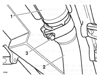
- Silencer
- Intermediate pipe
- Clamp
6. Support the silencer and release the bolt and nut securing the silencer mounting bracket to the rear frame.
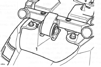
- Silencer mounting bracket fixing
7. Move the silencer rearwards to disengage it from the intermediate pipe and remove.
8. If the rear light bracket is to be removed, release the four silencer heatshield fixings and remove the two heatshields.
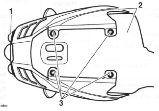
- Silencer
- Heatshields
- Fixings
9. Release the four fixings and remove the rear light bracket from the silencer.
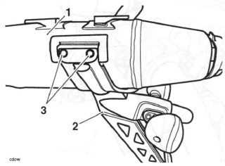
- Silencer
- Rear light bracket
- Fixings (left hand shown)
10. Remove the lower fairings.
11. Release the clamp securing the intermediate pipe to the header pipe.
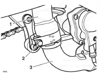
- Intermediate pipe
- Clamp
- Header pipe
12. Disconnect the oxygen sensor from the main harness.
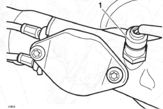
- Oxygen sensor
13. Remove the cover from the butterfly valve cables on the actuator.
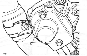
- Cover
- Fixings
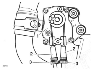
14. Slacken both cable adjusters at the actuator to give the maximum amount of slack in the cables.
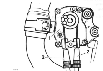
- Actuator
- Adjusters
15. Remove and discard the actuator pulley wheel fixing.
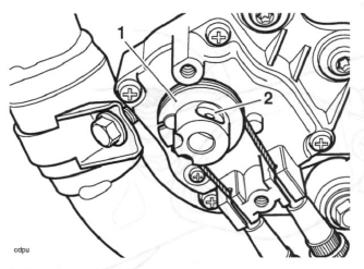
- Actuator pulley wheel
- Fixing
16. Slide the actuator pulley off the actuator shaft.
17. Slide the outer portion of the cables out of the actuator.
18. Detach the inner portion of the cables from the actuator pulley wheel.
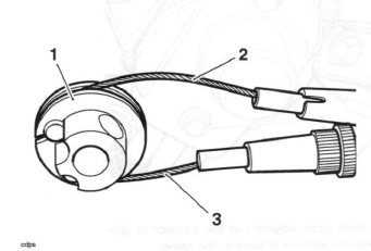
- Actuator pulley wheel
- Opening cable
- Closing cable
19. Remove the radiator.
20. Release the fixings securing the header pipe joints to the cylinder head. Discard the fixings.
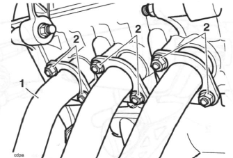
- Header pipes
- Fixings
21. Remove the bolt from the header pipe rear mounting point.
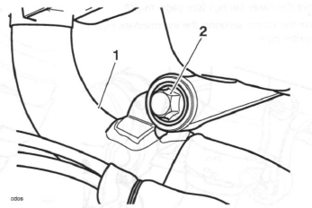
- Header pipe
- Header pipe rear mounting point
22. Detach the header pipe assembly and collect the seals from the cylinder head ports.
23. Remove the intermediate pipe fixing and remove the intermediate pipe downwards through the swinging arm.
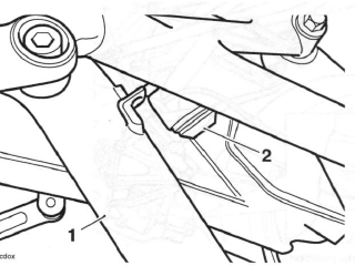
- Intermediate pipe
- Fixing
Inspection
1. Using an open ended spanner on the flats of the spindle, check that the exhaust valve in the header pipes is free to rotate and operates smoothly. If the exhaust valve is seized or does not operate smoothly, proceed as follows:
- Spray penetrating fluid into the spindle bushes of the butterfly valve, and again using an open-ended spanner on the flats of the spindle, turn the spindle end until it rotates freely.
- Once free, check the spindle end-float. The standard end-float is 0.5 to 1.5 mm but, if end float is less then 0.5 mm, the header pipes must be renewed.
- Once satisfied that the valve is in a serviceable condition, refit the header pipes to the motorcycle and adjust the butterfly valve cables.
Assembly
1. Refit the intermediate pipe upwards through the swinging arm and tighten the fixing to 22 Nm.
2. Fit new seals to the cylinder head. Ensure that the face of the seal with the tab is facing the cylinder head.
Note:
- A smear of grease may be used to retain the seals in the cylinder head during assembly.
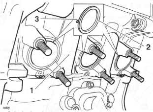
- Cylinder head
- Seals
- Seal tab
3. Locate the header pipes and align the header pipe flanges to the fixing points. Fit new nuts and hand tighten.
4. Assemble the rear mounting point fixing but do not tighten at this stage.
5. Tighten the header pipe to cylinder head nuts in the sequence shown below:
Up to VIN 381274
- Stage 1: Tighten the header pipe nuts in sequence to 2 Nm.
- Stage 2: Tighten the header pipe nuts in sequence to 19 Nm.
From VIN 381275
- Stage 1: Tighten the header pipe nuts in sequence to 2 Nm.
- Stage 2: Tighten the header pipe nuts in sequence to 15 Nm.
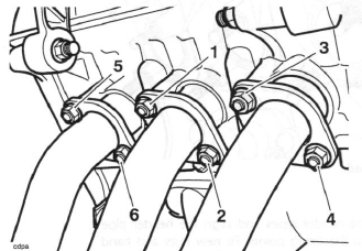
Header Pipe Tightening Sequence
6. Tighten the rear mounting point fixing to 19 Nm.
7. Refit the radiator and refill the cooling system.
8. Connect the butterfly valve control cables and pulley wheel to the actuator.
9. Adjust the butterfly valve control cables.
10. Refit the oxygen sensor and tighten to 25 Nm.
Warning: Incorrect alignment of the exhaust clamp may cause interference with the rear suspension which may lead to loss of motorcycle control and an accident.
11. Align the clamp to the intermediate to header pipe joint and tighten to 15 Nm. Ensure the clamp is aligned as shown below.
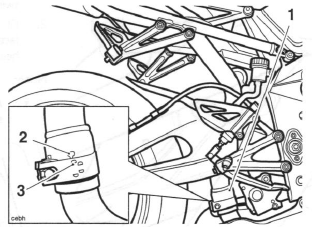
- Exhaust clamp position
- Exhaust cut-out
- Exhaust clamp alignment feature
12. If removed, refit the rear light bracket to the silencer.
Tighten the fixings to 12 Nm.
13. Refit the silencer heatshields. Tighten the fixings to 6 Nm.
14. Position and engage the silencer to the intermediate pipe. Ensure the front of the outer (cosmetic) heatshield is located over the two rubber mounting grommets on the rear subframe.
15. Align the silencer mounting bracket to the frame.
Tighten the fixing to 27 Nm.
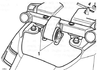
- Silencer mounting bracket fixing
Warning: Incorrect alignment of the exhaust clamp may cause interference with the rear suspension which may lead to loss of motorcycle control and an accident.
16. Align the clamp to the silencer to exhaust pipe joint and tighten to 15 Nm. Ensure the clamp is aligned as shown below.
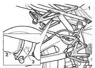
- Exhaust clamp position
- Exhaust cut-out
- Exhaust clamp alignment feature
17. Reconnect the battery, positive (red) lead first.
Caution: Do not install the exhaust system or run the engine without the exhaust heatshields fitted. Components protected by the exhaust heatshields may suffer severe damage or a fire if the motorcycle is operated without the heatshields being fitted.
18. Start the engine and check for exhaust gas leaks.
Rectify if necessary.
19. Refit the lower fairings.
20. Reconnect the direction indicator and licence plate la mp electrical connector.
21. Refit the rear bodywork.
22. Refit the seats.
Exhaust System - Street Triple and Street Triple R
Exhaust System - Street Triple and Street Triple R
Removal
Warning: If the engine has recently been running, the exhaust system will be hot. Before working on or near the exhaust system, allow sufficient time for the exhaust system to cool as touching any part of a hot exhaust system could cause burn injuries.
1. Remove the seat.
2. Disconnect the battery, negative (black) lead first.
3. Remove the rear bodywork.
4. Release the clamps securing the silencers to the intermediate pipe.
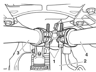
- Clamp bolts
- Intermediate pipe
- Left hand silencer
- Right hand silencer
5. Support the right hand silencer and release the bolt and nut securing the silencer mounting bracket to the rear frame.
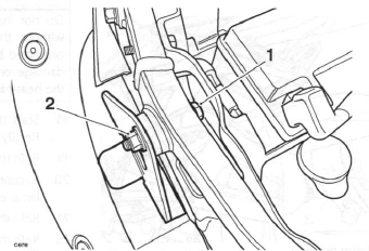
- Silencer mounting bracket fixing
- Nut
6. Move the silencer rearwards to disengage it from the intermediate pipe and remove. If fitted, collect the spacer from the rear subframe.
7. Repeat steps 5 and 6 above for the left hand silencer.
8. Release the clamp securing the intermediate pipe to the header pipes.
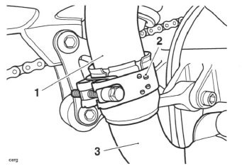
- Intermediate pipe
- Clamp
- Header pipes
9. Remove the intermediate pipe to rear subframe fixing.
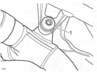
- Intermediate pipe fixing
10. Loosen the rear subframe lower fixings to the main frame.
11. With the aid of an assistant support the rear subframe.
12. Remove the rear subframe upper fixings to the main frame.
13. Carefully raise the rear subframe until the intermediate pipe can be released from the header pipe.
14. With the rear subframe still supported, manoeuvre the intermediate pipe until it can be removed upwards through the swinging arm, taking care not to damage the swinging arm or intermediate pipe as you do so.
15. Align the rear subframe to the frame and refit the fixings. Do not fully tighten at this stage.
16. Disconnect the oxygen sensor from the main harness. Release the oxygen sensor harness from its retaining points as shown below.
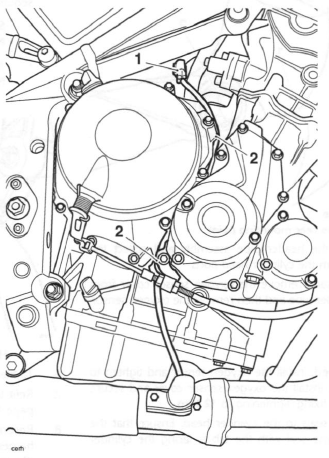
- Oxygen sensor connector
- Retaining points
17. Remove the radiator.
18. Release the fixings securing the header pipe joints to the cylinder head. Discard the fixings.
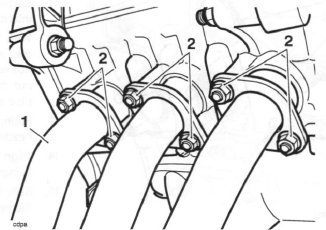
- Header pipes
- Fixings
19. Remove the bolt from the header pipe rear mounting point.
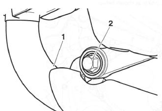
- Header pipe
- Header pipe rear mounting point
20. Detach the header pipe assembly and collect the seals from the cylinder head ports.
21. If necessary, remove the oxygen sensor cover from the header pipe and then remove the oxygen sensor.
Assembly
1. If removed, install the oxygen sensor and tighten to 25 Nm. Install the oxygen sensor cover and secure with the fixing, tightening to 12 Nm.
2. Fit new seals to the cylinder head. Ensure that the face of the seal with the tab is facing the cylinder head.
Note:
- A smear of grease may be used to retain the seals in the cylinder head during assembly.
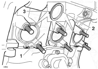
- Cylinder head
- Seal
- Seal tab
3. Locate the header pipes and align the header pipe flanges to the fixing points. Fit new nuts and hand tighten.
4. Assemble the rear mounting point fixing but do not tighten at this stage.
5. Tighten the header pipe to cylinder head nuts in the sequence shown below:
- Stage 1: Tighten the header pipe nuts to 2 Nm.
- Stage 2: Tighten the header pipe nuts to 19 Nm.
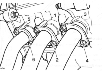
Header Pipe Tightening Sequence
6. Tighten the rear mounting point fixing to 19 Nm.
7. Refit the radiator and refill the cooling system.
8. Reconnect the oxygen sensor and secure the harness behind its retaining points as noted on disassembly.
9. With the aid of an assistant support the rear subframe.
10. Remove the rear subframe upper fixings to the main frame.
11. Carefully raise the rear subframe until the intermediate pipe can be installed.
12. With the rear subframe still supported, manoeuvre the intermediate pipe until in can be installed downwards through the swinging arm, taking care not the damage the swinging arm or intermediate pipe as you do so.
13. Position and engage the intermediate pipe to the header pipe.
14. Align the rear subframe to the frame and refit the fixings. Tighten all four subframe fixings to 48 Nm.
15. Refit the intermediate pipe to rear subframe fixing.
Tighten to 22 Nm.
Warning: Incorrect alignment of the exhaust clamp may cause interference with the rear suspension which may lead to loss of motorcycle control and an accident.
16. Align the intermediate pipe clamp to the header pipe as shown below and tighten to 15 Nm.
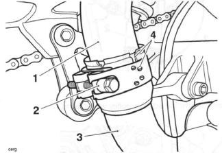
- Intermediate pipe
- Clamp
- Header pipe
- Alignment marks
17. Position and engage the right hand silencer to the intermediate pipe.
18. Refit the spacer (if removed) to silencer bolt in the rear subframe, and align the silencer mounting bracket to the spacer. Refit the nut. Tighten the fixings to 15 Nm.
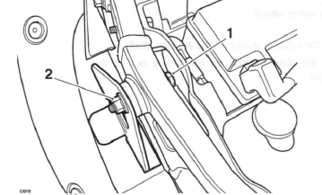
- Silencer mounting bracket fixing
- Nut
19. Repeat steps 17 and 18 above for the left hand silencer.
20. Align the intermediate pipe joint clamps such that the bolts are vertical as shown below, and tighten to 10 Nm.
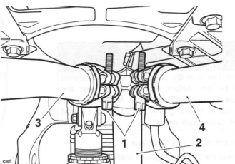
- Intermediate pipe joint clamps showing bolt alignment
- Header pipes
- Left hand silencer
- Right hand silencer
21. Reconnect the battery, positive (red) lead first.
Caution: Do not install the exhaust system or run the engine without the exhaust heatshields fitted. Components protected by the exhaust heatshields may suffer severe damage or a fire if the motorcycle is operated without the heatshields being fitted.
22. Start the engine and check for exhaust gas leaks.
Rectify if necessary.
23. Refit the rear bodywork.
24. Refit the seat.
Exhaust Butterfly Valve Actuator - Daytona 675 only
Removal
Warning: If the engine has recently been running, the exhaust system will be hot. Before working on or near the exhaust system, allow sufficient time for the exhaust system to cool as touching any part of a hot exhaust system could cause burn injuries.
1. Remove the rider's seat.
2. Disconnect the battery, negative (black) lead first.
3. Remove the right hand lower fairing.
4. Remove the cover from the butterfly valve cables on the actuator.
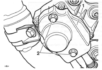
- Cover
- Fixings
5. Slacken both cable adjusters at the actuator to give the maximum amount of slack in the cables.
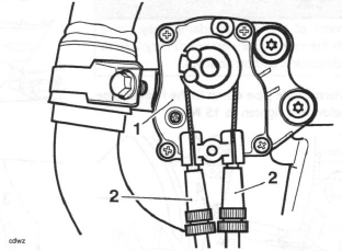
- Actuator
- Adjusters
6. Remove and discard the actuator pulley wheel fixing.
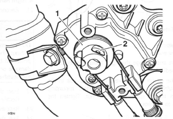
- Actuator pulley wheel
- Fixing
7. Slide the actuator pulley off the actuator shaft.
8. Slide the outer portion of the cables out of the actuator.
9. Detach the inner portion of the cables from the actuator pulley wheel.
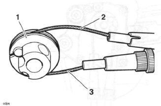
- Actuator pulley wheel
- Opening cable
- Closing cable
10. Release the two fixings and detach the actuator.
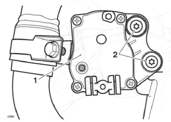
- Actuator
- Fixings
11. Disconnect the electrical connector and remove the actuator.
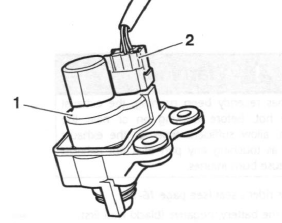
- Actuator
- Connector
Installation
1. Check that the exhaust valve in the header pipes is free to rotate and operates smoothly.
2. Position the actuator to the motorcycle and connect the electrical connector.
3. Refit the actuator to the frame and tighten the two fixings to 12 Nm.
4. Connect the butterfly valve control cables and pulley wheel to the actuator.
5. Adjust the butterfly valve control cables.
6. Refit the right hand lower fairing.
7. Reconnect the battery, red (positive) lead first.
8. Refit the rider's seat.
Exhaust Butterfly Valve Cables - Daytona 675 only
Removal
Warning: If the engine has recently been running, the exhaust system will be hot. Before working on or near the exhaust system, allow sufficient time for the exhaust system to cool as touching any part of a hot exhaust system could cause burn injuries.
1. Remove the rider's seat.
2. Disconnect the battery, negative (black) lead first.
3. Remove the right hand lower fairing.
4. Remove the cover from the butterfly valve cables on the actuator.
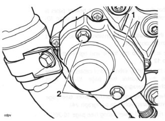
- Cover
- Fixings
5. Slacken both cable adjusters at the actuator to give the maximum amount of slack in the cables.
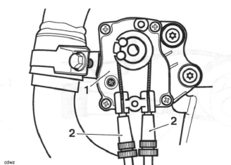
- Actuator
- Adjusters
6. Remove the cover from the butterfly valve cables on the exhaust header.
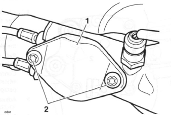
- Cover
- Fixings
7. Remove and discard the actuator pulley wheel fixing.
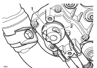
- Actuator pulley wheel
- Fixing
8. Slide the actuator pulley off the actuator shaft.
9. Slide the outer portion of the cables out of the actuator.
10. Detach the inner portion of the cables from the actuator pulley wheel.
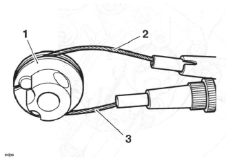
- Actuator pulley wheel
- Opening cable
- Closing cable
11. Slacken the adjuster locknuts at the exhaust valve end of the cables such that they will allow the outer cables to be detached from the exhaust headers.
Note:
- The adjuster/locknuts are coloured black on the upper, opening cable and silver on the lower, closing cable.
12. Noting the orientation of the cables, detach the inner cable nipples from the exhaust valve pulley wheel and remove the cables.
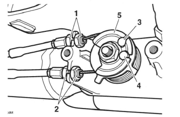
- Opening cable adjuster/locknuts
- Closing cable adjuster/locknuts
- Opening cable nipple
- Closing cable nipple
- Exhaust valve pulley wheel
Inspection
1. Check that both the exhaust valve cables operate smoothly, without sticking or binding. Replace the cables if there is any doubt as to their correct operation.
2. Using an open ended spanner on the flats of the spindle, check that the exhaust valve in the header pipes is free to rotate and operates smoothly. If the exhaust valve is seized or does not operate smoothly, proceed as follows: 3. Remove the header pipes.
4. Spray penetrating fluid into the spindle bushes of the butterfly valve, and again using an open-ended spanner on the flats of the spindle, turn the spindle end until it rotates freely.
5. Once free, check the spindle end-float. The standard end-float is 0.5 to 1.5 mm but, if end float is less then 0.5 mm, the header pipes must be renewed.
6. Once satisfied that the valve is in a serviceable condition, refit the header pipes to the motorcycle and adjust the butterfly valve cables.
Installation
1. Insert the cable threaded ends into the exhaust headers as noted on removal, ensuring the adjuster/ locknuts are positioned one on either side of the cable retainer casting on the exhaust header. Do not tighten the adjuster/locknuts at this stage.
Note:
- For identification, the adjuster/locknuts are coloured black on the upper, opening cable and silver on the lower, closing cable.
2. Fit the cable nipples into the exhaust valve pulley wheel.
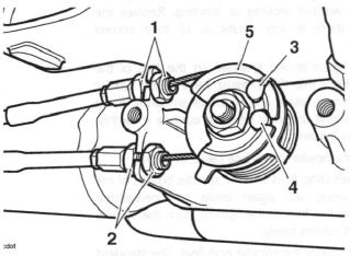
- Opening cable adjuster/locknuts
- Closing cable adjuster/locknuts
- Opening cable nipple
- Closing cable nipple
- Exhaust valve pulley wheel
Note:
- Where the outer cables locate into the actuator, the cable outer sleeve is coloured black on the upper, opening cable and silver on the lower, closing cable.
3. Fit the inner portion of the cables to the actuator pulley wheel, ensuring the pulley wheel is installed with the fixing boss facing outwards, and the opening (black) cable uppermost.
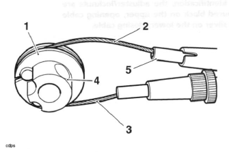
- Actuator pulley wheel (fixing boss facing outwards)
- Opening cable
- Closing cable
- Fixing boss
- Black coating on cable outer
4. Insert the outer portion of the cables into the actuator.
5. Slide the actuator pulley onto the actuator shaft.
6. Install a new actuator pulley wheel fixing and tighten to 5 Nm.
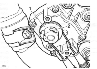
- Actuator pulley wheel
- Fixing
7. Adjust the exhaust valve cables.
8. Refit the right hand lower fairing.
9. Reconnect the battery, red (positive) lead first.
10. Refit the rider's seat.
Exhaust Butterfly Valve Cable Adjustment - Daytona 675 only
Warning: If the engine has recently been running, the exhaust system will be hot. Before working on or near the exhaust system, allow sufficient time for the exhaust system to cool as touching any part of a hot exhaust system could cause burn injuries.
1. Remove the rider's seat.
2. Disconnect the battery, negative (black) lead first.
3. Remove the right hand lower fairing.
4. Remove the cover from the butterfly valve cables on the actuator.
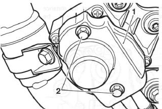
- Cover
- Fixings
5. Slacken both cable adjusters at the actuator to give the maximum amount of slack in the cables.
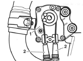
- Actuator
- Adjusters
6. Remove the cover from the butterfly valve cables on the exhaust header.
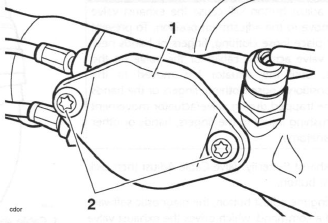
- Cover
- Fixings
7. Slacken the butterfly valve cable locknuts and, using the adjuster nuts, set the distance between the end of the cables and the cable retainer casting on the exhaust header to 5 mm. Tighten the locknuts to 5 Nm.
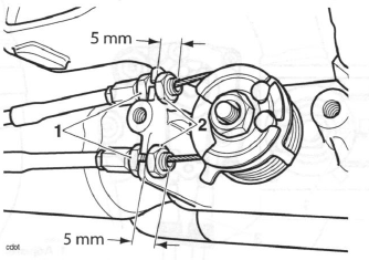
- Locknuts
- Adjuster nuts
8. Reconnect the battery, red (positive) lead first.
9. Attach the Triumph diagnostic tool to the dedicated plug, refer to the Triumph Diagnostic Tool User Guide.
10. Turn the ignition to the 'ON' position.
11. On the diagnostic software navigate to and select the 'ADJUST TUNE' option.
Warning: Clicking the adjust button will cause the exhaust valve actuator to move to the adjustment position. To prevent injury, never place loose clothing, fingers or hands near the exhaust valve actuator, cables or the valve on the header pipe, until the actuator has moved to the adjustment position. Loose clothing, fingers or the hands could become trapped during valve/actuator movement and cause crushing injury to the fingers, hands or other parts of the anatomy.
12. Select Exhaust Butterfly Valve Cable Adjust then click the adjust button.
13. On clicking the adjust button, the diagnostic software will send a command, which drives the exhaust valve actuator to the middle position. The diagnostic software will then show adjust cable on the screen.
Click the OK button.
14. The exhaust butterfly cables can now be adjusted as follows: 15. Turn the adjuster shown in the illustration below until the butterfly valve pulley wheel arrow is level with the lower edge of the butterfly valve 'stop casting.
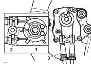
- Butterfly valve pulley wheel arrow
- Butterfly valve 'stop' casting
- Adjuster
16. Turn the adjuster shown in the illustration below to remove the slack from the cables. Measure the cable slack as follows:
- Using light finger pressure, squeeze the cables together at the position shown below.
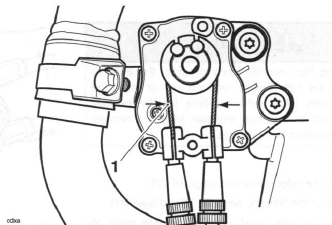
- Cable slack measurement position
- Whilst maintaining light finger pressure, measure the distance between the two cables.
- When the cable slack is correct, the distance between the two cables should be 12 - 14 mm.
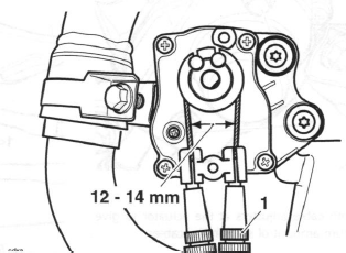
- Adjuster
- Correct setting, 12 - 14 mm
17. Tighten the cable adjuster locknuts.
- Actuator
- Adjusters
- Locknuts
Warning: Clicking the OK button will cause the exhaust valve actuator to move to the closed position and then the fully open position. To prevent injury, never place loose clothing, fingers or hands near the exhaust valve actuator, cables or the valve on the header pipe, until the actuator has stopped. Loose clothing, fingers or the hands could become trapped during valve/actuator movement and cause crushing injury to the fingers, hands or other parts of the anatomy.
18. On the diagnostic software, click the OK button to return the actuator to normal control and return the diagnostic software to the 'ADJUST TUNE' menu.
Note:
- If the cable adjustment procedure has been correctly carried out, the exhaust valve will now be in the closed position.
- If the adjustment is not correct, the exhaust valve will be set in the open position and the Malfunction Indicator Light (MIL) will be illuminated, indicating the presence of DTCs (Diagnostic Trouble Codes).
- The following screen will be displayed:
19. Rectify the DTCs as necessary by repeating the adjustment procedure.
20. On the diagnostic software, scroll to the 'DIAGNOSTICS' menu and select 'READ STORED DTCS', refer to the Triumph Diagnostic Tool User Guide. Re-check for any stored DTCs and rectify as necessary.
21. Turn the ignition to the 'OFF' position.
22. Disconnect the Triumph diagnostic tool.
23. Refit the cover to the butterfly valve cables on the actuator. Tighten the fixings to 2 Nm.
24. Refit the cover to the butterfly valve cables on the exhaust header. Tighten the fixings to 12 Nm.
25. Refit the right hand lower fairing.
26. Refit the rider's seat.
See also:
 Triumph Street Triple S - Service manual > Idle Speed Control Stepper Motor
Removal 1. Remove the rider's seat. 2. Disconnect the battery, negative (black) lead first. 3. Remove the fuel tank. 4. Remove the airbox.
 Triumph Street Triple S - Service manual > Secondary Air Injection
System Purpose and Operation The secondary air injection system is an aid to reducing levels of pollutants in the exhaust gases. It does this by introducing a small amount of air into each exhaust port as the exhaust valve opens. The introduced air helps promote further combustion of the fuel mixture in the exhaust system after it has left the combustion chamber.

 Benelli Imperiale 400
 BMW F900XR
 Honda CB500X
 KTM 390 Adventure
 Triumph Street Triple S
 Yamaha MT-03
 Kawasaki Z400
 Triumph Street Triple S
 Yamaha MT-03