 Kawasaki Z400 - Service manual > Fuel System (DFI)
Air Cleaner Element Replacement
NOTE
Oln dusty areas, the element shouhi be replad more frequently than the recommended interval.
WARNING
If dirt or dust is allowed to pass through into the throttle body assy, the throttle may become stuck, possibly causing accident. Replace the air cleaner element according to tho maintenance chart.
NOTICE
If dirt gets through into the engine, excessive engine wear and possibly engine damage will occur.
- Remove:
- Fuel Tank (see Fuel Tank Removal in the Fuel System (DFI) chapter
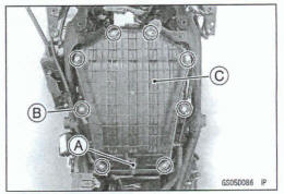
Disconnect the intake air temperature sensor connector [A].
- Remove:
Air Cleaner Housing Assembly Screws [B]
Upper Air Cleaner Housing [C]
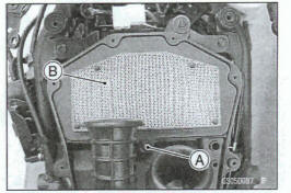
- Remove the air cleaner element mounting screw [A].
- Discard the air cleaner element [B].
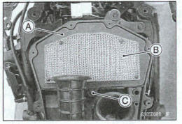
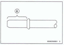
- Install a new element [A] so that the screen side [B] faces upward.
- Tighten:
Torque -Air Cleaner Element Mounting Screw [C]: 1.2 N*m (0.12 kgf*m, 11 in-lb)
- Install: Upper Air Cleaner Housing
- Tighten: Torque -Air Cleaner Housing Assembly Screws: 1.2 N.m (0.12 kgf*m, 11 in-lb)
- Connect the intake air temperature sensor connector.
- Install: Fuel Tank (see Fuel Tank Installation in the Fuel System (DFI) chapter)
Idle Speed Inspection
- Start the engine and warm it up thoroughly.
- With the engine idling, turn the handlebars to both sides [A].
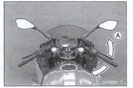
*If handlerbars movement changes the idle speard, the throttle cables may be improperly adjusted or incorrectly routed or damaged. Be sure to correct any of these conditions before riding (see Throttle Control System Inspection and Cable, Wire, and Hose Routing section in the Appendix chapter).
WARNING
Operation with improerly adjusted, incorrectly routed or damaged cables could result in an unsafe riding Condition. Follow the service manual to be make sure to correct any of these conditions.
- Check the idle speed.
ldle Speed Standard: 1300+- r/min (rpm)
*If the idle speed is out of specified range, check the idle speed control valve actuator (see ldle Speed Control Valve Actuator Resistance lnspsction in the Fuel System (DFI) chapter).
Idle Speed Adjustment
NOTE
This motorcycle is equipped with the idle speed control valve actuator. The idle speed is adjusted automatically at the specified value (1 300 +-50r/min I(rpm)) by the idle speed control valve system. Therefore, it is not necessary to adjust the idle speed normally
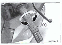
Throttle Control System Inspection
- Check that the throttle grip [A] moves smoothly from full open to close, end the throttle closes quickly and completely by the return spring in all steering positions.
*If the throttle grip does not return properly, check the throttle cable routing, grip free play, and cable damage. Then lubricate the throttle cable
- Check the throttle grip free play.
Throttle Grip Free Play Standard: 2 - 3 mm (0.08 - 0.12 in.)
If the free play incorect, adjust the throttle cable as follows.
- Remove the left middle fairing (see Middle Fairing Removal in the Frame chapter).
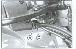
- Loosen the locknuts [A] [B].
- Screw both throttle cable adjusters [C] [D] to give the throffle grip plenty of play.
- Turn the decelerator cable adjuster [D] until it has no play when the throttle grip is completely dosed.
- Tighten the locknut [B].
- Turn the accelerator cable adjuster [C] until 2 - 3 mm (0.08 - 0.12 in.) of throttle grip play is obtained.
- Tighten the locknut [A].
If the free play can not be adjusted with the adjusters, replace the cable.
- Install the removed parts (see appropriate chapters).
Engine Vacuum Synchronization Inspection
NOTE
These pdumar e explained on the assumption that the intake and exhaust systems of the engine are in good condition
- .Situate the motorcycle so that it is vertical.
- Remove: Air Cleaner Housing (see Air Cleaner Housing Removal in the Fuel System (DFI) chapter)
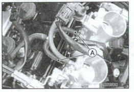
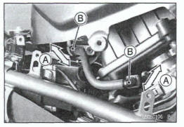
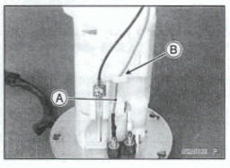
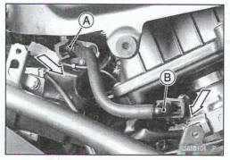
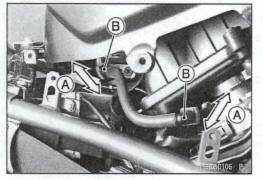
- Pull off the rubber caps or vacuum hoses [A] from the fittings of each throttle body.
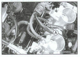
- The evaporative emission control system equipped models are equipped the vacuum hoses.
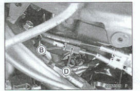
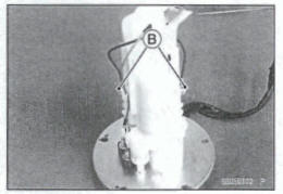
- Connect a vacuum gauge and hoses [A] (Specid Tool: 57001-1369) to the fittings on the throttle body.
Special Tool - Vacuum Gauge: 57001-1369
- Conned a highly accurate tachometer lead [B] to one of the stick coil primary leads.
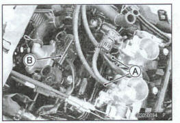
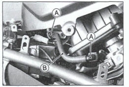
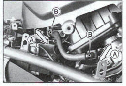
Plug the air switching valve hose end (A) and air cleaner housing fitting (B)
- Install: Air Cleaner Housing (see Air Cleaner Housing Installation in the Fuel System (DFI) chapter) Fuel Tank (see Fuel Tank Installaition in the Fuel System (DFI)chapter)
- Start the wine and warm it up thoroughly.
- Check the idle speed, using a highly accurate tachometer.
Idle Speed Standard: 1 300+-50 r/min (rpm)
NOTICE
Do not measure the idle speed by the tachometr of the metrunit.
- While idling the engine, inspect the throttle body vacuum, using the vacuum gauge.
Throttle Body Vacuum Standard: 36.0+-1.33 kPa (270 +-10 mmHg) at idle speed
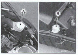
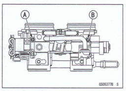
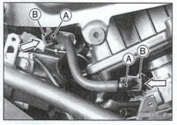
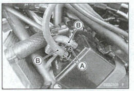
If any vacuum is not within specifications, adjust the bypass screws #1 [A] and #2 [B].
Special Tool - Pilot Screw Adjuster A, [C]: 57001-1239
- Adjust the each vacuum (#1, #2)I to, the standard value.
- Open and close the throtle valves after each measurement.
- Check the vacuum as before
If all vacuums are within the specification range, finish the engine vacuum synchronization.
If any vacuum can not be adjusted within the specifocation, replace the bypass screws #1 and #2 with new ones, refer to the following procedure.
Remove the thrattle body assy (see Throttle Body Assy Removal in the Fuel System (DFI) chapter).
Turn in the bypass screw [A] with counting the number of tums until it seals fully but not tightly. Record the number of tums.
Remove:
Byppas Screw
Spring [B] Washer [C] O-ring [D]
- Check the bypass screw hole in the throttle body for carbon deposits.
If any carbons accumulate, wipe the carbons off from the hole, using a cotton pad penetrated with a high flash-point solvent
- Replace the bypass screw, spring, washer and O-ring as a set.
- Turn in the bypass screw until it seats fully but not tightly.
NOTICE
Do not over-tighten the bypass screw. The tapered portion [E] of the bypass screw could be damaged.
- Back out the same number of tums counted when first turned in. This is to set the screw to its original position.
NOTE
A throttle body assy has diferent "tums out" of the bypass screw for each individual unit. On setting the bypass screw, use the 'turns out' determined during disassembly.
- Repeat the same procedure for other bypass screw.
- Repeat the synchronization.
If the vacuums are correct, check the output voltage of the throttb sensor (see Throttle Sensor Output Voltage Inspection in the Fuel System (DFI) chapter).
Special Tool - Throttle Sensor Setting Adapter 57001 -1 538
Throttle Sensor Output Voltage Connections to Adapter:
Digital Meter (+) - R (sensor Y/W) lead
Digital Meter (-) - W (sensor BR/BK) lead
Standard: DC 1.00 - 1.02 V at idle throttle opening
If the output voltage is out of the standard, check the input voltage of the throttle sensor (see Throttle Sensor Input Voltage Inspection in the Fuel System (DFI) chapter).
- Remove the vacuum gauge hoses and install the rubber caps or vacuum hoses to the original position.
- The evaporative emission control system equipped models are equipped the vacuum hoses.
- Run the vacuum hoses according to Cable, Wire, and Hose Routing section in the Appendix chapter.
- Install the removed parts (see appropriate chapters).
Fuel System Inspection
Fuel Hose Inspection (fuel leak, damage, Installation condition)
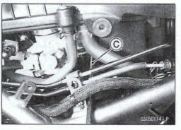
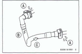
- If the motorcycle is not properly handled, the high pressure inside the fuel line can cause fuel to leak [A] or the hose to burst. Remove the right middle fairing (see Middle Fairing Removal in the Frame chapter) and check the fuel hose
Replace the fuel hose if any fraying, cracks [B] or bulges [C] are noticed
- Check that the hose is routed according to Cable, Wire, and Hose Routing section in the Appendix chapter.
*Replace the hose if it has been sharply bent or kinked.
Hose Joints [A] Fuel Hose [B]
- Check that the fuel hose joints are securely connected.
- Push and pull [A] the fuel hose joint [B] back and forth more than two times, and make sure it is locked and does not come off.
WARNING
Leaking fuel can cause a fire or explosion resulting in serious burns. Make sure the hose joint is installed correctly on the delivery pipe by sliding the joint.
If it does not lock, reinstall the hose joint.
Fuel Filter Replacement
WARNING
Gasoline is extremely flammable and can be explosive under certain conditions, creating the potential for serious burns. Make sure the area is well ventilated and free from any source of flame or sparks; this includes any appliance with a pilot light. Do not smoke. Turn the ignition switch off. Disconnect the battery (-) terminal. To avoid fuel spills, draw it from the tank when the engine is cold. Be prepared for fuel spillage; any spilled fuel must be completely wiped up immediately.
NOTICE
Never drop the fuel pump especially on a hard surface.
Such a shock to the pump can damage it.
- Remove
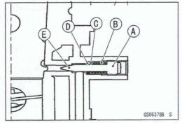
Fuel Pump (see Fuel Pump Removal in the Fuel System (DFI) chapter) Fuel Pump Assy Screw [A] Lead Terminal [B] Plate Nut [C
- Disconnect: Lead Terminal (Red) [D] Lead Terminal (Light Blue) [E]
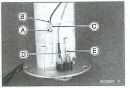
- Remove: Fuel Pump Assy Screw [A] Lead Terminal [B] Plate Nut [C]
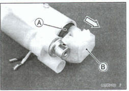
- Using the flat tip driver [A], clear he tabs [B], and remove the fuel pump fitting [C] from the case [D].
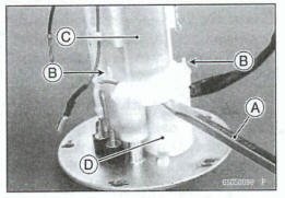
- Remove the fuel pump body [A] with fuel filter [B] from the fitting.
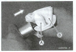
- Wrap the fuel filter (A) with the clean cloth (B) and remove the fuel filter.
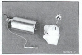
Replace the fuel filter [A] with a new one.
- Replace the following parts with new ones and install the
removed parts in the reverse procedure.
O-rings [A] Fuel Pump Assy Screws [B]
- Tighten: Torque - Fuel Pump Assy Screws: 0.98 Nm (0.10 kgf*m, 8.7 In-lb) '
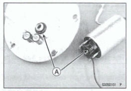
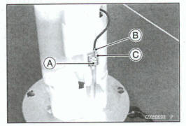
Run the lead [A] into the guide [B].
Fuel Hose Replacement
WARNING
Fuel is flammable and explosive under certain conditions and can cause severe burns. Be prepared for fuel spillage; any spilled fuel must be completely wiped up immediately. When the fuel hose is disconnected, fuel spills out from the hose and the pipe because of residual pressure. Cover the hose connection with a piece of clean cloth to prevent fuel spillage.
NOTICE
When removing and installing the fuel hose joint, do not apply strong force to the outlet pipe on the fuel pump and delivery pipe on the throttle body assy.
The pipes made from resin could be damaged.
- Remove the right middle fairing (see Middle Fairing Removal in the Frame chapter).
- Be sure to place a piece of cloth around the fuel hose joint.
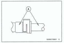
- Wipe off the dirt of the surface (A) around the connection using a cloth or a soft brush.
When removing with flat tip screwdriver
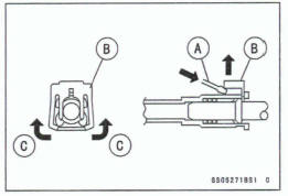
- Insert the flat tip screwdriver [A] into slit on the joint lock (B).
- Turn the driver to disconnect the joint lock.
When removing with fingers
- Open and push up [C] the joint lock with your fingers
NOTICE
Prying or excessively widening the joint lock ends for fuel hose removal will permanently deform the joint lock, resulting in a loose or incomplete lock that may allow fuel to leak and create the potential for a fire explosion. To prevent fire or explosion from a damaged joint lock, do not pry or excessively widen the joint lock ends when removing the fuel hose. The joint lock has a retaining edge that locks around the housing.
- Pull the fuel hose joint [A] out of the outlet pipe.
- Pull the fuel hose joint [B] out of the delivery pipe.
- Clean the outlet pipe and delivery pipe.
- Cover the outlet pipe and delivery pipe with the vinyl bags to keep them clean.
- Remove the vinyl bags on the pipe.
- Check that there are no flaws, burrs, and adhesion of foreign materials on the pipe [A].
- Replace the fuel hose with a new one
- Insert the fuel hose joint [A] straight onto the pipe until the hose joint clicks.
- Push the joint lock [B] until the hose joint clicks.
- Push and pull [A] the fuel hose joint [B] back and forth more than two times, and make sure it is locked and does not come off.
WARNING
Leaking fuel can cause a fire or explosion resulting in serious burns. Make sure the hose joint is installed correctly on the delivery pipe by sliding the joint.
If it comes off, reinstall the hose joint
- Start the engine and check the fuel hose for leaks.
Evaporative Emission Control System Inspection (Equipped Models)
- Inspect the canister as follows.
- Remove the left middle fairing (see Middle Fairing Removal in the Frame chapter).
- Slide the clamps [A].
- Disconnect the hoses [B].
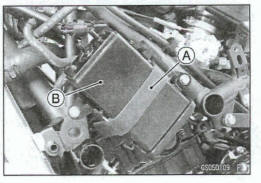
- Remove: Band [A] Canister [B]
- Visually inspect the canister for cracks or other damage
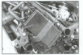
If the canister has any cracks or bad damage, replace it with a new one.
NOTE
The canister is designed to work well through the motorcycle's life without any maintenance if it is used under noma1 conditions.
- Inspect the purge valve (see Purge Valve Inspection in the Fuel System (DFI) chapter).
- Check that the hoses are securely connected and champs are in position.
- Replace any kinked, deteriorated or damaged hoses.
- Run the hoses according to Cable, Wire, and Hose Routing section in the Appendix chapter.
- When installing the hoses, avoid sharp bending, kinking, flattening or twisting, and run the hoses with a minimum of bending so that the emission flow will not be obstructed.
See also:
 Kawasaki Z400 - Service manual > Cooling System
Coolant Level Inspection NOTE Check the level when the engine is cold (room or ambient temperature). Check the coolant level in the reserve tank with the motorcycle held perpendicular (Do not use the sidestand.).
 Benelli Imperiale 400
 BMW F900XR
 Honda CB500X
 KTM 390 Adventure
 Triumph Street Triple S
 Yamaha MT-03
 Kawasaki Z400
 Triumph Street Triple S
 Yamaha MT-03