 Yamaha MT-03 - Service manual > Fuel injection system
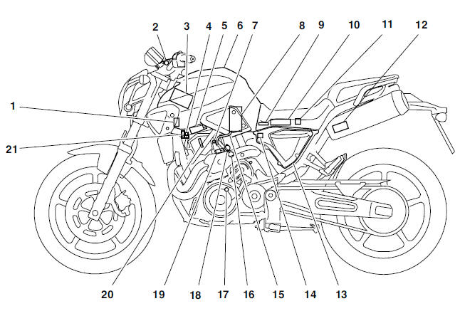
- Fuel injection system relay
- Engine trouble warning light
- Battery
- Air induction system solenoid
- Ignition coil/Spark plug
- Fuel tank
- Idling adjustment screw
- Fuel pump
- Intake air pressure sensor
- ECU
- Lean angle cut-off switch
- Catalytic converter
- Air filter case
- Intake air temperature sensor
- Fuel hose
- Coolant temperature sensor
- Crankshaft position sensor
- Throttle position sensor
- Fuel injector
- Spark plug
- Air cut-off valve
Wiring diagram
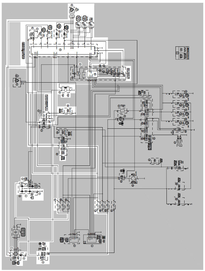
1. Crankshaft position sensor
3. Neutral switch
4. Main switch
7. Battery
8. Main fuse
14. Fuel injection system relay
16. Ignition coil
17. Spark plug
18. Fuel injector
19. Air induction system solenoid
20. Intake air temperature sensor
21. Coolant temperature sensor
22. ECU
23. Speed sensor
24. Throttle position sensor
25. Intake air pressure sensor
26. Lean angle cut-off switch
27. Multi-function meter unit
36. Engine trouble warning light
37. Fuel pump
38. Sidestand switch
41. Engine stop switch
67. Ignition fuse
70. Fuel injection system fuse
Ecu's self-diagnostic function
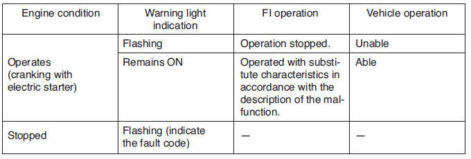
The ECU is equipped with a self-diagnostic function in order to ensure that the engine control system is operating normally. If this function detects a malfunction in the system, it immediately operates the engine under substitute characteristics and illuminates the engine trouble warning light to alert the rider that a malfunction has occurred in the system. Once a malfunction has been detected, a fault code is stored in the memory of the ECU.
- To inform the rider that the fuel injection system is not functioning correctly, the engine trouble warning light flashes when the start switch is being pushed to start the engine.
- If a malfunction is detected in the system by the self-diagnostic function, this mode provides an appropriate substitute characteristic operation, and alerts the rider of the detected malfunction by illuminating the engine trouble warning light.
- After the engine has been stopped, the lowest fault code number displays on the FI diagnostic tool. This fault code remains stored in the memory of the ECU until it is deleted.
- Engine trouble warning light
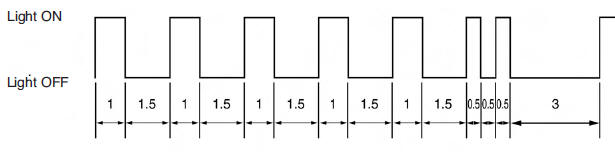
Engine trouble warning light fault code indication
Digit of 10: Cycles of 1 sec. ON and 1.5 sec. OFF.
Digit of 1: Cycles of 0.5 sec. ON and 0.5 sec. OFF.
<Example> 42
Engine trouble warning light indication and FI system operating condition
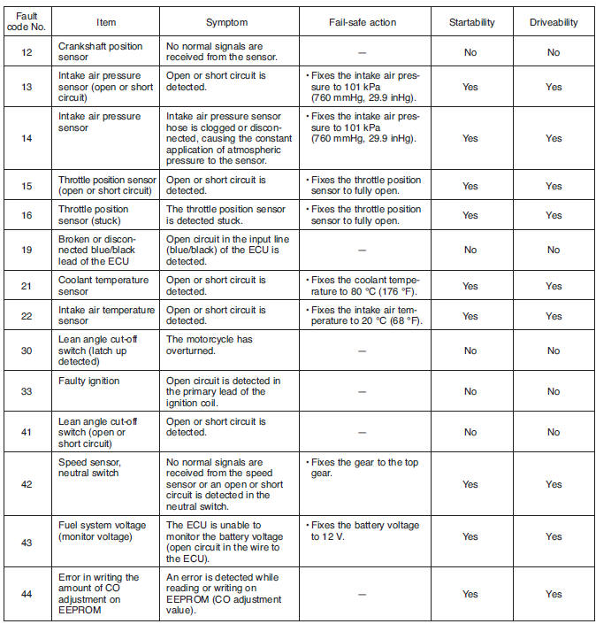
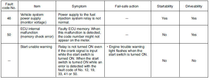
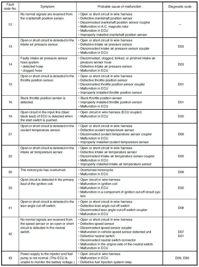
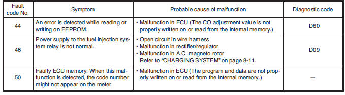
Self-diagnostic function table
If the ECU detects an abnormal signal from a sensor while the vehicle is being driven, the ECU illuminates the engine trouble warning light and provides the engine with alternate operating instructions that are appropriate for the type of malfunction.
When an abnormal signal is received from a sensor, the ECU processes the specified values that are programmed for each sensor in order to provide the engine with alternate operating instructions that enable the engine to continue to operate or stop operating, depending on the conditions.
Fail-safe action table
Self-diagnostic function
Troubleshooting chart
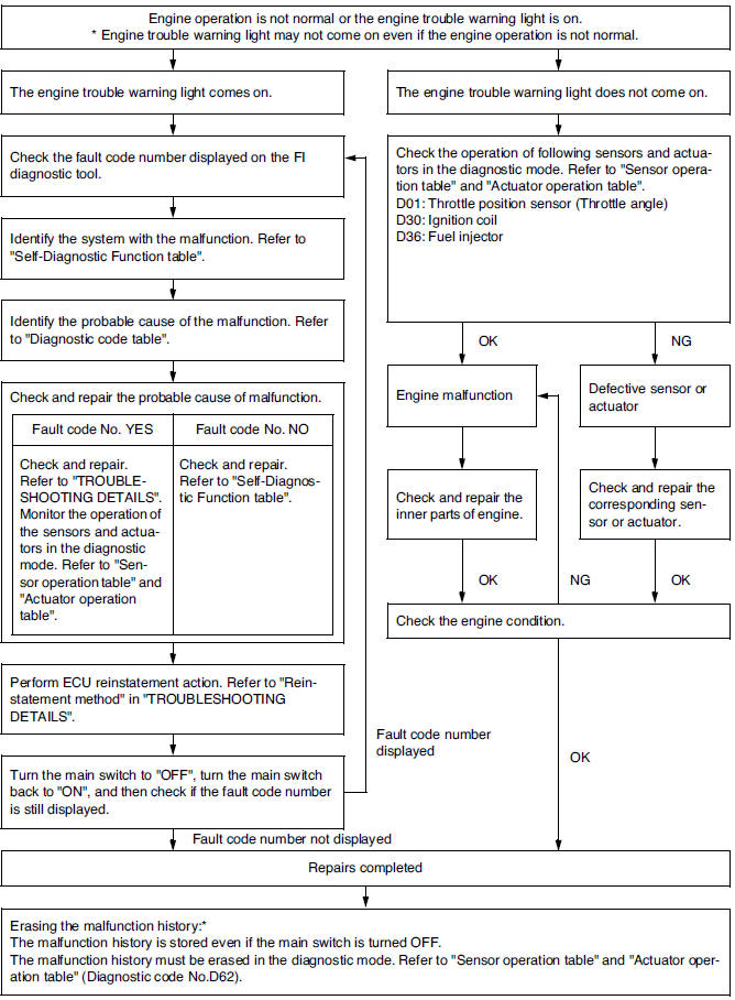
* Operated when the engine trouble warning light is on.
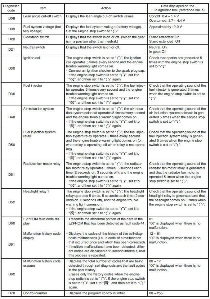
Diagnostic mode
It is possible to monitor the sensor output data or check the activation of actuators with the FI diagnostic tool connected to the vehicle and set to the normal mode or the diagnostic monitoring mode.
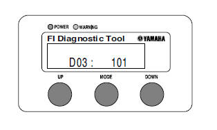
 FI diagnostic tool
90890-03182
FI diagnostic tool
90890-03182
Setting the normal mode
NOTE:
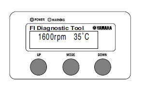
The engine speed, engine temperature, and fault code, if detected, can be displayed on the LCD of the FI diagnostic tool when the tool is connected to the vehicle and is set to the normal mode.
1. Turn the main switch to "OFF" and set the engine stop switch to "RUN".
2. Remove the self-diagnosis signal coupler cap, and then connect the FI diagnostic tool "1" as shown.
3. Turn the main switch to "ON" and start the engine.
NOTE:
- Coolant temperature and engine revolution appear on the LCD of the FI diagnostic tool.
- "POWER" LED (Green) comes on.
- If a malfunction is detected in the system, "WARNING" LED (Orange) comes on.
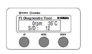
4. Stop the engine.
NOTE:
If a malfunction is detected in the system, the fault code appears on the LCD of the FI diagnostic tool. And also, "WARNING" LED (Orange) comes on.
5. Turn the main switch to "OFF" to cancel the normal mode.
6. Disconnect the FI diagnostic tool and connect the self-diagnosis signal connector.
Setting the diagnostic mode
1. Turn the main switch to "OFF" and set the engine stop switch to "RUN".
2. Remove the self-diagnosis signal coupler cap, and then connect the FI diagnostic tool "1" as shown.
3. While press the "MODE" button, turn themain switch to "ON".
NOTE:
- "DIAG" appears on the LCD of the FI diagnostic tool.
- "POWER" LED (Green) comes on.
4. Press the "UP" button to select the CO adjustment mode "CO" or the diagnostic mode "DIAG".
5. After selecting "DIAG", press the "MODE" button.
6. Select the diagnostic code number corre sponding to the fault code number by pressing the "UP" and "DOWN" buttons.
NOTE:
- The diagnostic code number appears on the LCD (D01-D70).
- To decrease the selected diagnostic code number, press the "DOWN" button. Press the "DOWN" button for 1 second or longer to automatically decrease the diagnostic code numbers.
- To increase the selected diagnostic code number, press the "UP" button. Press the "UP" button for 1 second or longer to automatically increase the diagnostic code numbers.
7. Verify the operation of the sensor or actuator.
- Sensor operation.
The data representing the operating conditions of the sensor appear on the LCD.
- Actuator operation.
Set the engine stop switch to "OFF" and then to "RUN".
8. Turn the main switch to "OFF" to cancel thediagnostic mode.
9. Disconnect the FI diagnostic tool and connect the self-diagnosis signal connector.
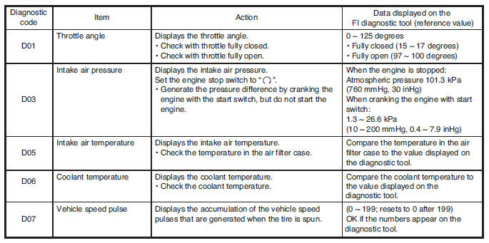
Diagnostic monitoring code table
Diagnostic mode table
Switch the meter display from the regular mode to the diagnostic mode. To switch the display, refer to "DIAGNOSTIC MODE".
NOTE:
- Check the intake air temperature and coolant temperature as close as possible to the intake air temperature sensor and the coolant temperature sensor respectively.
- If it is not possible to check the intake air temperature, use the ambient temperature as reference.
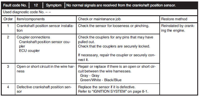
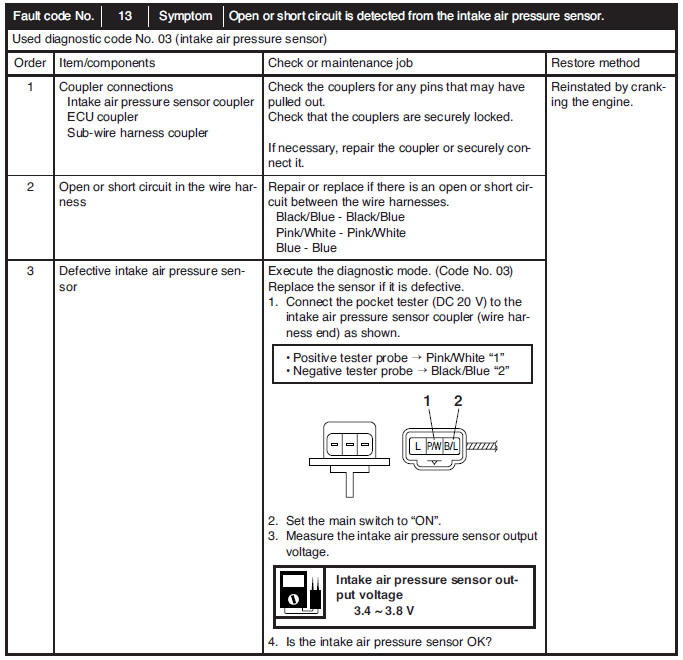
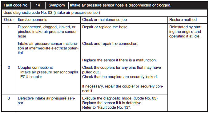
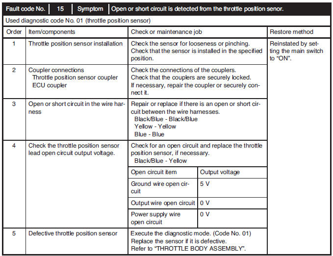
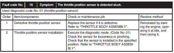
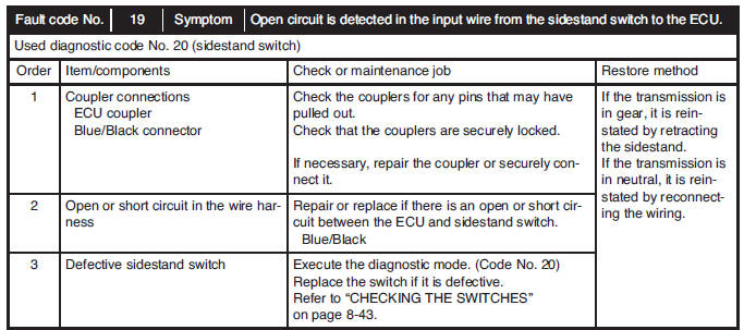
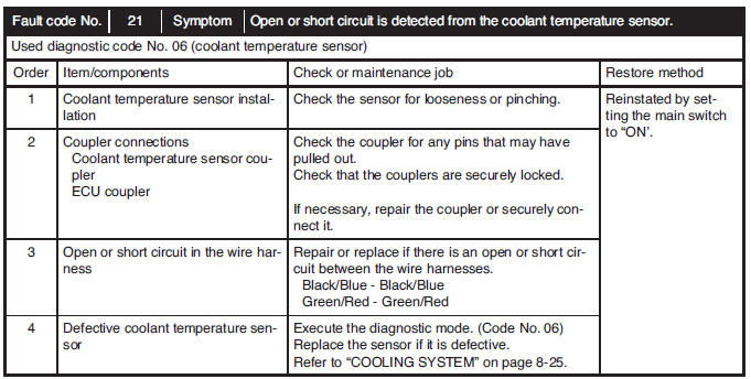
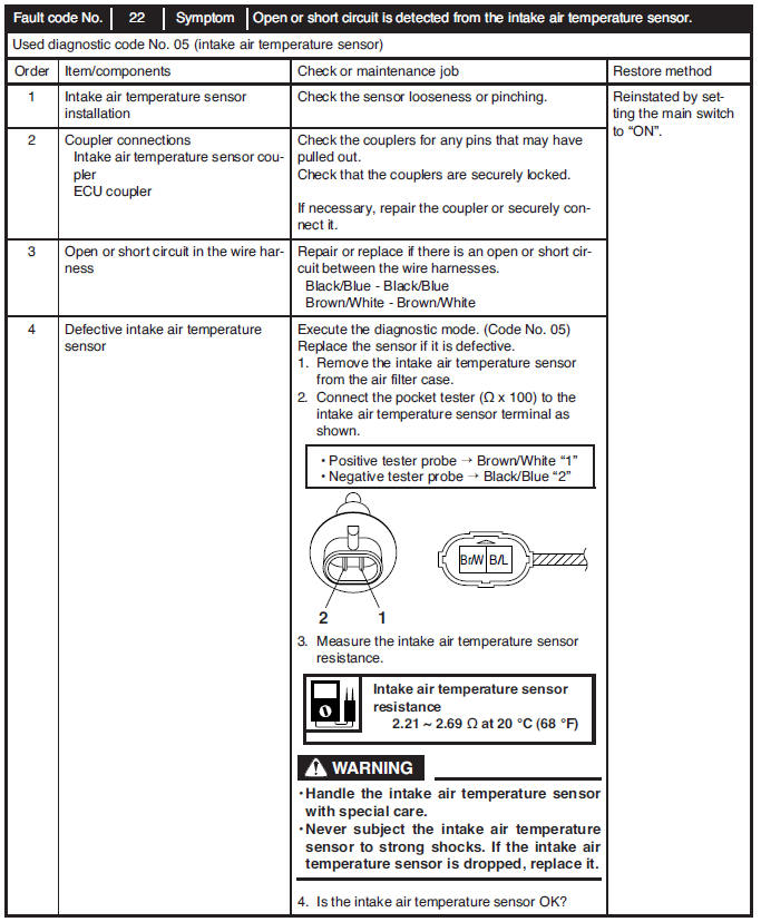
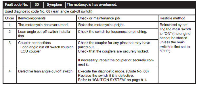
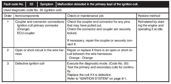
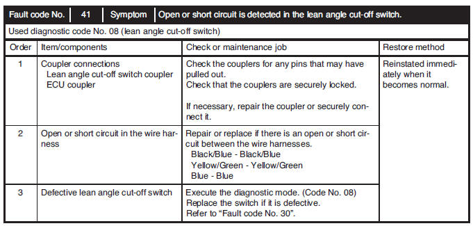
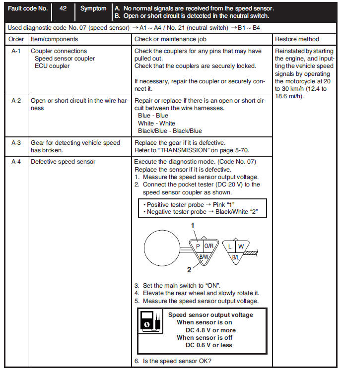
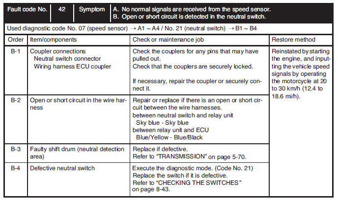
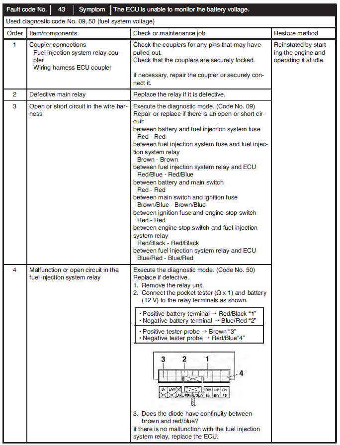
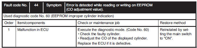
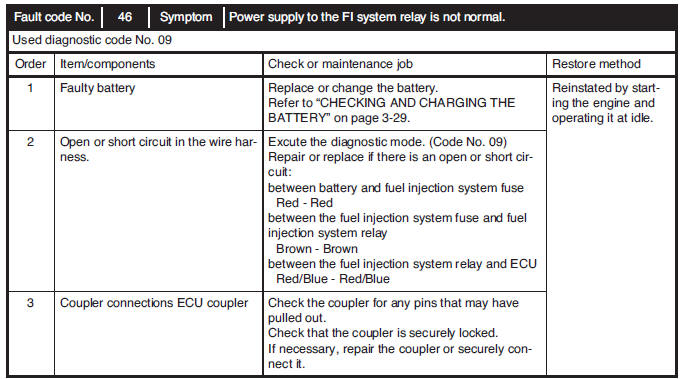
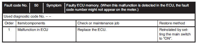
Troubleshooting details
This section describes the countermeasures per fault code number displayed on the FI diagnostic tool. Check and service the items or components that are the probable cause of the malfunction following the order given.
After the check and service of the malfunctioning part has been completed, reset the FI diagnostic tool display according to the "Reinstatement method".
Fault code No.: Fault code number displayed on the FI diagnostic tool when the engine failed to work normally.
Refer to "Diagnostic code table".
Diagnostic code No.: Diagnostic code number to be used when the diagnostic mode is operated. Refer to "DIAGNOSTIC MODE".
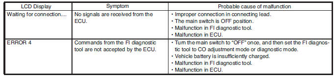
Communication error with the FI diagnostic tool
See also:
 Yamaha MT-03 - Service manual > Fuel tank
Removing the fuel tank 1. Extract the fuel in the fuel tank through the fuel tank cap with a pump.
Yamaha MT-03 - Service manual > Electrical system
Ignition system Circuit diagram 1. Crankshaft position sensor
 Benelli Imperiale 400
 BMW F900XR
 Honda CB500X
 KTM 390 Adventure
 Triumph Street Triple S
 Yamaha MT-03
 Kawasaki Z400
 Triumph Street Triple S
 Yamaha MT-03