 Yamaha MT-03 - Service manual > Fuel tank
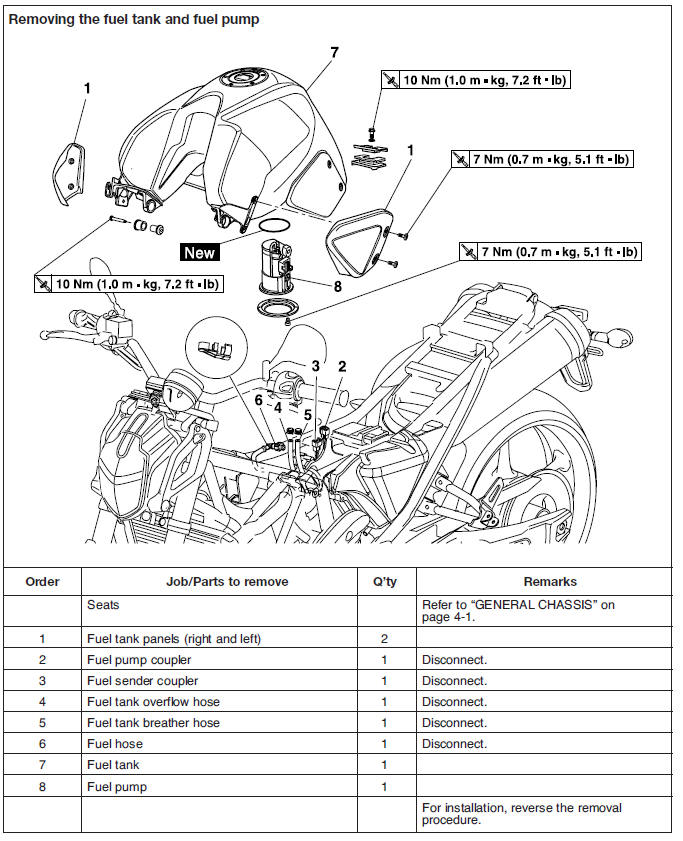
Removing the fuel tank
1. Extract the fuel in the fuel tank through the fuel tank cap with a pump.
2. Remove:
- Seats
- Bolts "1"
- Panels "2" (right and left)
3. Remove:
- Fuel tank rear bolt "3"
4. Remove:
- Fuel tank front bolts "4"
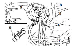
5. Remove:
- Fuel hose clamps "5"
6. Disconnect:
- Overflow pipes "6"
- Fuel hose "7"
- Fuel pump coupler "8"
- Fuel sender coupler "9"
CAUTION:
Although the fuel has been removed from the fuel tank be careful when removing the fuel hoses, since there may be fuel remaining in them.
NOTE:
- If Remove the fuel hose manually without using any tools.
- Before removing the hoses, place a few rags in the area under where they will be removed.
7. Remove:
- Fuel tank
NOTE:
Do not set the fuel tank down on the installation surface of the fuel pump. Be sure to lean the fuel tank against a wall or the like.
Removing the fuel pump
1. Remove:
- Fuel pump
CAUTION:
- Do not drop the fuel pump or give it a strong shock.
- Do not touch the base section of the fuel sender.
Installing the fuel pump
1. Install:
- Fuel pump
NOTE:
- Do not damage the installation surfaces of the fuel tank when installing the fuel pump.
- Always use a new fuel pump gasket.
- Align the projection "A" on the fuel pump with the slot in the fuel pump bracket.
- Tighten the bolts to the specified torque in the proper tightening sequence as shown.
- Install the fuel pump in the direction shown in the illustration.
2. Tighten:
- Fuel pump bolts
 Fuel pump bolt
7 Nm (0.7 m*kg, 5.1 ft*lb)
Fuel pump bolt
7 Nm (0.7 m*kg, 5.1 ft*lb)
Installing the fuel hose
1. Install:
- Fuel hose
CAUTION:
When installing the fuel hose, be sure to securely connect it.
Checking the fuel sender
This model is equipped with a self-diagnosis device for the fuel sender circuit. If the fuel sender circuit is defective, the following cycle will be repeated until the malfunction is corrected.
- The fuel level warning light will flash four times and then go off for 3.0 seconds if the fuel sender circuit is in short circuit.
- The fuel level warning light will flash eight times and then go off for 3.0 seconds if the fuel sender circuit is interrupted or the coupler disconnected.
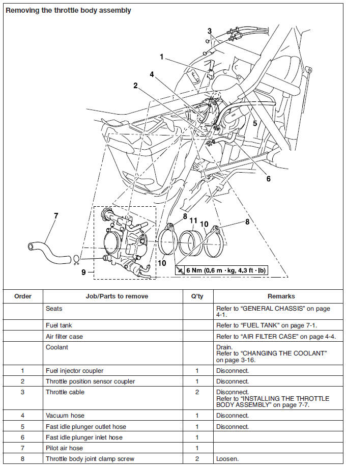
Throttle body assembly
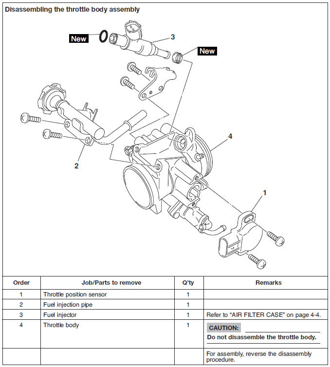
Checking the fuel injector
1. Check:
- Fuel injector.
Damage → Replace.
2. Check:
- Fuel injector resistance
a. Disconnect the injection wire harness coupler from the fuel injector.
b. Connect the pocket tester (Ω x 1) to the fuel injector terminal as shown.
- Positive tester probe → Red/Black "1"
- Negative tester probe → Red/Blue "2"
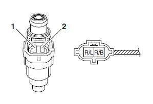
c. Measure the fuel injector resistance.
Out of specification → Replace the fuel injector.
 Fuel injector resistance
12 Ω at 20 ºC (68 ºF)
Fuel injector resistance
12 Ω at 20 ºC (68 ºF)
Checking the throttle body
1. Check:
- Throttle body.
Cracks/damage → Replace the throttle body.
2. Check:
- Fuel passages.
Obstructions → Clean.
a. Wash the throttle body in a petroleum-based solvent.
CAUTION:
Do not use any caustic carburetor cleaning solution.
b. Blow out all of the passages with compressed air.
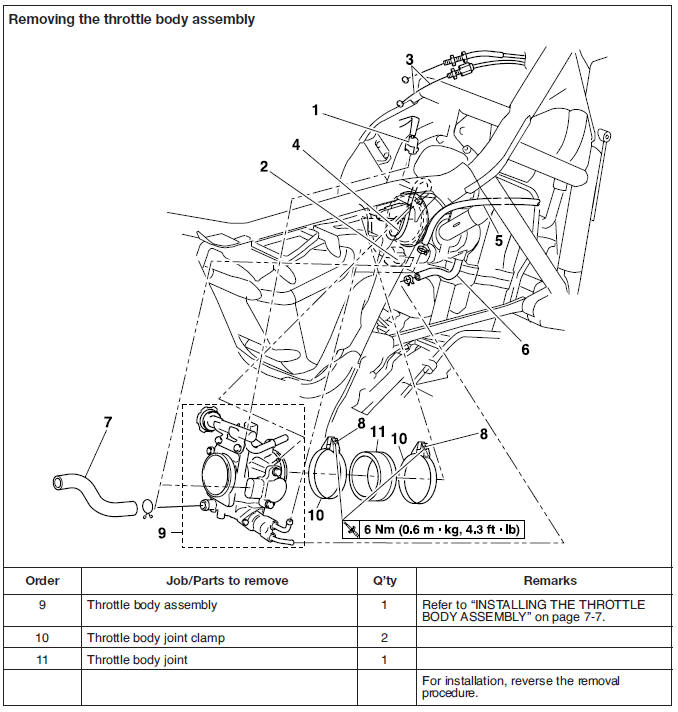
Installing the throttle body assembly
1. Install:
- Throttle body joint clamps
NOTE:
Align the projection "a" on the throttle body joint with the slot "b" in the throttle body joint clamp.
2. Install:
- Throttle body joint
NOTE:
Align the projection "a" on the cylinder head with the slot "b" in the throttle body joint.
3. Install:
- Throttle body assembly
NOTE:
Align the projection "a" on the throttle body assembly with the slot "b" throttle body joint.
4. Install:
- Throttle cable
5. Adjust:
- Throttle lever free play
6. Adjust:
- Engine idling speed
7. Check:
- Throttle position sensor
Checking the fuel pump
WARNING
Gasoline is extremely flammable and under certain circumstances there can be a danger of an explosion or fire. Be extremely careful and note the following points:
- Stop the engine before refueling.
- Do not smoke, and keep away from open flames, sparks, or any other source of fire.
- If you do accidentally spill gasoline, wipe it up immediately with dry rags.
- If gasoline touches the engine when it is hot, a fire may occur. Therefore, make sure the engine is completely cool before performing the following test.
1. Check:
- Fuel pump operation
a. Fill the fuel tank.
b. Put the end of the fuel hose into an open container.
c. Connect a battery (DC 12 V) to the fuel pump coupler as shown.
- Positive battery lead → Red/Blue "1"
- Negative battery lead → Black "2"
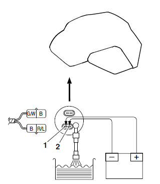
d. If fuel flows out of the fuel hose, the fuel pump is OK. If fuel does not flow, replace the fuel pump.
2. Check:
- Fuel pressure
a. Remove the fuel tank.
Refer to "FUEL TANK" on page 7-1.
b. Connect the pressure gauge "1" to the adapter "2".
c. Connect the fuel pressure adapter to the fuel pump and fuel hose "3".
 Pressure gauge
90890-03153
Fuel pressure adapter
90890-03176
Pressure gauge
90890-03153
Fuel pressure adapter
90890-03176
d. Connect the fuel pump coupler "4" and fuel sender coupler "5" to the fuel pump.
e. Set the main switch to "ON" and the engine
stop switch to " ".
".
f. Start the engine.
g. Measure the fuel pressure.
 Fuel pressure
324 kPa (3.24 kg/cm2, 46.1 psi)
Fuel pressure
324 kPa (3.24 kg/cm2, 46.1 psi)
Out of specification → Replace the fuel pump.
Checking and adjusting the throttle position Sensor
NOTE:
Before adjusting the throttle position sensor, the engine idling speed should be properly adjusted.
1. Check:
- Throttle position sensor (removed from the throttle body)
a. Disconnect the throttle position sensor coupler from the throttle position sensor.
b. Remove the throttle position sensor from the throttle body.
c. Connect the pocket tester (Ω x 1k) to the throttle position sensor.
- Positive tester probe → Terminal "1"
- Negative tester probe → Blue Black/Blue terminal "2"
d. Measure the maximum throttle position sensor resistance.
Out of specification → Replace the throttle position sensor.
 Maximum throttle position
sensor
resistance
4.0-6.0 kΩ at 20 ºC (68 ºF)
(blue-black/blue)
Maximum throttle position
sensor
resistance
4.0-6.0 kΩ at 20 ºC (68 ºF)
(blue-black/blue)
e. Connect the pocket tester (Ω x 1k) to the throttle position sensor.
- Positive tester probe → Yellow terminal "3"
- Negative tester probe → Black/Blue terminal "2"
f. While slowly opening the throttle, check that the throttle position sensor resistance is within the specified range.
The resistance does not change or it changes abruptly → Replace the throttle position sensor.
The slot is worn or broken → Replace the throttle position sensor.
NOTE:
Check mainly that the resistance changes gradually when turning the throttle, since the readings (from closed to wide-open throttle) may differ slightly from those specified.
 Throttle position sensor
resistance
0-5 +- 1.0 kΩ at 20 ºC (68 ºF)
(yellow-black/blue)
Throttle position sensor
resistance
0-5 +- 1.0 kΩ at 20 ºC (68 ºF)
(yellow-black/blue)
2. Adjust:
- Throttle position sensor angle
a. Connecting the throttle position sensor coupler to the wire harness.
b. Connect the digital circuit tester to the throttle position sensor.
- Positive tester probe → Yellow terminal "1"
- Negative tester probe → Black/Blue terminal "2"
 Digital circuit tester
90890-03174
Digital circuit tester
90890-03174
c. Measure the throttle position sensor voltage.
d. Adjust the throttle position sensor angle so the measured voltage is within the specified range.
 Throttle position sensor
voltage
0.63-0.73 V
(yellow-black/blue)
Throttle position sensor
voltage
0.63-0.73 V
(yellow-black/blue)
e. After adjusting the throttle position sensor angle, tighten the throttle position sensor screws.
Air induction system
Air injection
The air induction system burns unburned exhaust gases by injecting fresh air (secondary air) into the exhaust port, reducing the emission of hydrocarbons.
When there is negative pressure at the exhaust port, the reed valve opens, allowing secondary air to flow into the exhaust port. The required temperature for burning the unburned exhaust gases is approximately 600 to 700 ºC (1,112 to 1,292 ºF).
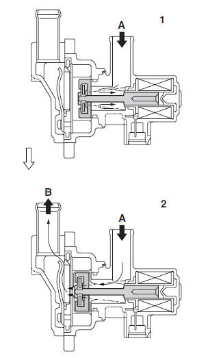
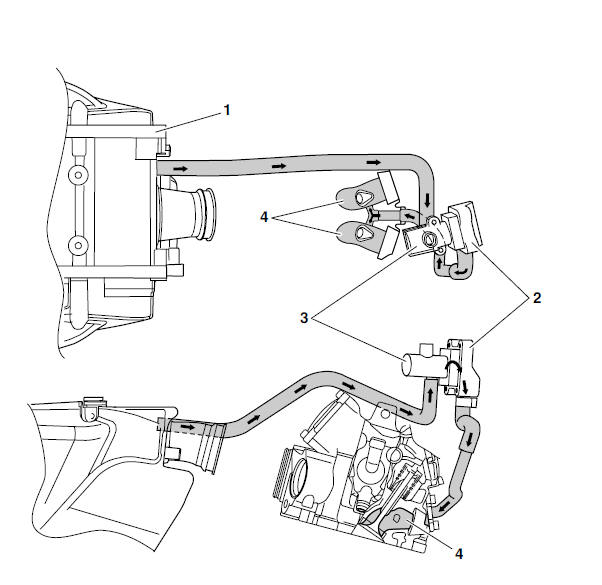
Air cut-off valve
The air cut-off valve is controlled by the signals from the ECU in accordance with the combustion conditions. Ordinarily, the air cut-off valve opens to allow the air to flow during idle and closes to cut-off the flow when the vehicle is being driven. However, if the coolant temperature is below the specified value, the air cut-off valve remains open and allows the air to flow into the exhaust pipe until the temperature becomes higher than the specified value.
A. From the air filter case
B. To the cylinder head
1. The air cut-off valve is closed.
2. The air cut-off valve is open.
Air induction system diagrams
1. Air filter case
2. Reed valve
3. Air cut-off valve
4. Exhaust port
Air cut-off valve assembly
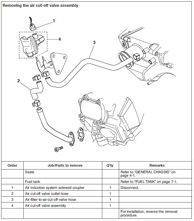
Checking the air induction system
1. Check:
- Hoses.
Loose connections → Connect properly.
Cracks/damage → Replace.
- Pipe Cracks/damage → Replace.
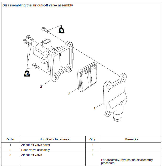
2. Check:
- Reed valve
- Reed valve stopper
- Reed valve seat
- Cracks/damage → Replace the reed valve assembly.
3. Check:
- Air cut-off valve Cracks/damage → Replace.
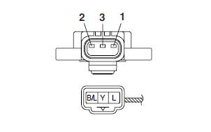
4. Check:
- Air induction system solenoid
a. Remove the air induction system solenoid coupler from the air cut-off valve assembly.
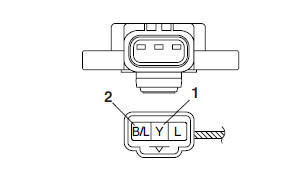
b. Connect the pocket tester (Ω x 1) to the air induction system solenoid terminal as shown.
- Positive tester probe → Brown/Red "1"
- Negative tester probe → Red/White "2"
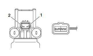
c. Measure the air induction system solenoid resistance.
Out of specification → Replace the air cut-off valve assembly.
 Air induction system solenoid
resistance
18-22 Ω at 20 ºC (68 ºF)
Air induction system solenoid
resistance
18-22 Ω at 20 ºC (68 ºF)
See also:
 Yamaha MT-03 - Service manual > Fuel injection system
Fuel injection system relay Engine trouble warning light Battery Air induction system solenoid Ignition coil/Spark plug Fuel tank Idling adjustment screw Fuel pump Intake air pressure sensor ECU Lean angle cut-off switch Catalytic converter Air filter case Intake air temperature sensor Fuel hose Coolant temperature sensor Crankshaft position sensor Throttle position sensor Fuel injector Spark plug Air cut-off valve
 Benelli Imperiale 400
 BMW F900XR
 Honda CB500X
 KTM 390 Adventure
 Triumph Street Triple S
 Yamaha MT-03
 Kawasaki Z400
 Triumph Street Triple S
 Yamaha MT-03