 Triumph Street Triple S - Service manual > Fuel Handling Precautions
General
The following information provides basic precautions which must be observed if petrol (gasoline) is to be handled safely. It also outlines other areas of risk which must not be ignored. This information is issued for basic guidance only and, if in doubt, appropriate enquiries should be made of your local Fire Officer.
Petrol - Gasoline
When petrol (gasoline) evaporates it produces 150 times its own volume in vapour which when diluted with air becomes a readily ignitable mixture. The vapour is heavier than air and will always fall to the lowest level. It can readily be distributed throughout any indoor environment by air currents, consequently, even a small spillage of petrol (gasoline) is potentially very dangerous.
Warning: Petrol (gasoline) is highly flammable and can be explosive under certain conditions. When opening the fuel tank cap always observe all the following items: Turn the motorcycle ignition switch OFF.
Do not smoke.
Always have a fire extinguisher containing FOAM, CO2, HALON or POWDER close at hand when handling or draining fuel or fuel systems. Fire extinguishers must also be present in areas where fuel is stored.
Always disconnect the vehicle battery, negative (black) lead first, before carrying out dismantling or draining work on a fuel system.
Whenever petrol (gasoline) is being handled, drained, stored or when fuel systems are being dismantled, make sure the area is well ventilated. All potential forms of ignition must be extinguished or removed (this includes any appliance with a pilot light). Any lead-lamps must be flame-proof and kept clear of any fuel spillage.
Warning notices must be posted at a safe distance from the site of the work to warn others that petrol is being openly handled. The notice must instruct the reader of the precautions which must be taken.
Failure to observe any of the above warnings may lead to a fire hazard which could result in personal injury.
Warning: No one should be permitted to repair components associated with petrol/gasoline without first having specialist training on the fire hazards which may be created by incorrect installation and repair of items associated with petrol/gasoline.
Repairs carried out by untrained personnel could bring about a safety hazard leading to a risk of personal injury.
Warning: Draining or extraction of petrol/gasoline from a vehicle fuel tank must be carried out in a well ventilated area.
The receptacle used to contain the petrol/ gasoline must be more than adequate for the full amount of fuel to be extracted or drained. The receptacle should be clearly marked with its contents, and placed in a safe storage area which meets the requirements of local authority regulations.
When petrol/gasoline has been extracted or drained from a fuel tank, the precautions governing naked lights and ignition sources should be maintained.
Failure to observe any of the above warnings could bring about a safety hazard leading to a risk of personal injury.
Fuel Tank Removal
Fuel tanks should have a 'PETROL (GASOLINE) VAPOUR' warning label attached to them as soon as they are removed from the vehicle. In all cases, they must be stored in a secured, marked area.
Chassis Repair
Warning If the motorcycle is involved in an accident or collision it must be taken to an authorised Triumph dealer for repair or inspection. Any accident can cause damage to the motorcycle, which if not correctly repaired, may cause a second accident which may result in injury or death.
The frame must not be modified as any modification to the frame such as welding or drilling may weaken the frame resulting in an accident.
Electrical Precautions
The following guidelines are intended to ensure the safety of the operator whilst preventing damage to the electrical and electronic components fitted to the motorcycle.
Where necessary, specific precautions are detailed in the relevant sections of this manual which should be referred to prior to commencing repair operations.
Equipment - Prior to commencing any test procedure on the motorcycle ensure that the relevant test equipment is working correctly and any harness or connectors are in good condition, in particular mains leads and plugs.
Warning: The ignition system produces extremely high voltages.
Do not touch any part of the ignition system or any cables while the engine is running.
An electric shock caused by contact with the ignition system may lead to illness, injury or death.
Warning: Wearers of surgically implanted heart pacemaker devices should not be in close proximity to ignition circuits and or diagnostic equipment.
The ignition system and any diagnostic equipment may interrupt the normal operation of such devices causing ill ness or death.
Warning: The battery contains harmful materials. Always keep children away from the battery whether or not it is fitted in the motorcycle.
Do not jump start the battery, touch the battery cables together or reverse the polarity of the cables as any of these actions may cause a spark which would ignite battery gasses causing a risk of personal injury.
High Voltage Circuits - Whenever disconnecting live High Tension (H.T.) circuits always use insulated pliers. Exercise caution when measuring the voltage on the coil terminals while the engine is running, high voltage spikes can occur on these terminals.
Connectors and Harness - The engine of a motorcycle is a particularly hostile environment for electrical components and connectors. Always ensure these items are dry and oil free before disconnecting and connecting test equipment.
Never force connectors apart either by using tools or by pulling on the wiring itself. Always ensure locking mechanisms are disengaged before removal and note the orientation to enable correct reconnection. Ensure that any protective covers and substances are replaced if disturbed.
Having confirmed a component to be faulty, switch off the ignition and disconnect the battery negative (black) lead first. Remove the component and support the disconnected harness. When replacing the component keep oily hands away from electrical connection areas and push connectors home until any locking mechanism becomes fully engaged.
Battery Disconnecting
Before disconnecting the battery, switch off all electrical equipment.
Warning: To prevent the risk of a battery exploding and to prevent damage to electrical components ALWAYS disconnect the battery negative (black) lead first. When reconnecting the battery, always connect the positive (red) lead first, then the negative (black) lead. Always disconnect the battery when working on any part of the electrical system.
Failure to observe the above warnings may lead to electrical damage and a fire hazard which could cause personal injury.
Always ensure that battery leads are routed correctly and are not close to any potential chafing points.
Disciplines
Switch off the ignition prior to making any connection or disconnection in the system. An electrical surge can be caused by disconnecting 'live connections which can damage electronic components.
Ensure hands and work surfaces are clean and free of grease, swarf, etc. as grease collects dirt which can cause tracking or high-resistance contacts.
Prior to commencing any test, and periodically during any test, touch a good earth to discharge body static. This is because some electronic components are vulnerable to static electricity.
Electrical Wires
All the electrical wires are either single-colour or two-colour and, with only a few exceptions, must be connected to wires of the same colour. On any of the two-colour wires there is a greater amount of one colour and a lesser amount of a second colour. A two-colour wire is identified by first the primary colour and then the secondary colour. For example, a yellow wire with thin red stripes is referred to as a 'yellow/red' wire; it would be a 'red/yellow' wire if the colours were reversed to make red the main colour.
Electrical Testing
For any electrical system to work, electricity must be able to flow in a complete circuit from the power source (the battery) via the components and back to the battery. No circuit means no electrical flow. Once the power has left the positive side of the battery and run through the component it must then return to the battery on its negative side (this is called earth or ground). To save on wiring, connections and space, the negative side of the battery is connected directly to the frame or engine.
Around the frame and engine will be various other ground points to which the wiring coming from components will be connected. In the case of the starter motor it bolts directly to the engine, which is bolted to the frame. Therefore the frame and engine also form part of the earth return path.
Ohm's Law
The relationship between voltage, current and resistance is defined by Ohm's Law.
- The potential of a battery is measured in Volts (V).
- The flow of current in a circuit (I) is measured in Amperes.
- The power rating of a consumer is measured in Watts (W).
- The resistance (R) of a circuit is measured in Ohms (Ω).
Ohms law, for practical work can be described as - 
Power is calculated by multiplying Volts x Amps - 
By transposing either of these formulae, the value of any unit can be calculated if the other two values are known.
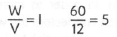
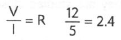
For example, if a battery of 12V is connected to a bulb of 60W:
-
the current flowing in the circuit can be calculated by using -
-
the bulb resistance can be calculated by using -
To use either of the following triangles, put your finger over
the value you want to find. Multiply the remaining values if side-by-side, or
divide if one is over the other. 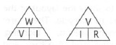
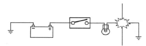
Basic Electrical Circuits
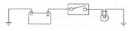
Basic Circuit Diagram
In the above circuit an electrical reservoir (the battery) is connected via a cable to a terminal on the controlling device (the switch) whose contacts are either open or closed. The other terminal on the switch is connected via a cable to the consumer (the bulb), and the other side of the bulb filament is connected to ground (earth) by another cable. The ground point is usually a part of the frame or engine, to which the battery negative terminal is also connected.
When the switch contacts are open (as shown in the diagram), the circuit is broken and no current flows. When the switch contacts are closed the circuit is made and current flows from the battery positive terminal through the switch contacts and bulb filament to ground. The frame completes the circuit to the battery negative terminal and the bulb illuminates.
Although some circuits on the circuit diagram may at first seem more complicated, it will generally be found that they can be broken down into sections which do not differ greatly from the basic circuit above.
Circuit Diagrams
Circuit diagrams are created to provide a 'picture' of the electrical system and to identify the route taken by each individual wire through the system, in order to identify which components it feeds and which connectors the wire runs through. Circuit diagrams are an essential tool for fault finding, as it is possible to locate start and finish points for a circuit without having to manually trace the wire through the motorcycle itself. Circuits diagrams may look confusing at first but when they are studied closely they soon become logical.
Due to the complex circuits and the number of individual wires, Triumph uses two types of circuit diagram in its service manuals.
- Within the manual conventional circuit diagrams are used to show the layout of the main circuits of the motorcycle. These are: Engine management/ignition, Lighting, Starting and Charging and Auxiliary and Accessory. In these diagrams no attempt is made to show the components of the system in any particular order or position in relation to the motorcycle.
- At the back of the service manual a full colour layout circuit diagram is used to show the main electrical components in a position similar to the actual position on the motorcycle.
Both of these circuit diagrams use similar symbols to illustrate the various system components and will be accompanied by a key to circuit diagram components and wiring colour codes.
Circuit diagrams also depict the inner workings of a switch cube (I.E. which wire connects to which when a switch is turned from one position to another) so that a test of that switch can be made using the wire terminals in the connector instead of disassembling the switch itself.
Glossary of Circuit Diagram Symbols
The following is a description of the symbols found in the circuit diagrams used in all Triumph service manuals.
The following is a description of the symbols found in the circuit diagrams used in all Triumph service manuals.
Connector
 This
illustration is used to show all multi-plug type electrical connectors on
Triumph circuit diagrams. The numbers in the box relate to the terminal numbers
of the connector pins. On ECMs with two connectors, the number would be prefixed
with the letters A or B to identify each connector. An additional number outside
the box will identify the component.
This
illustration is used to show all multi-plug type electrical connectors on
Triumph circuit diagrams. The numbers in the box relate to the terminal numbers
of the connector pins. On ECMs with two connectors, the number would be prefixed
with the letters A or B to identify each connector. An additional number outside
the box will identify the component.
Diode
 An
electrical one-way valve. Diodes allow current to flow in one direction but will
not allow it to return. The arrow, which forms part of the diode symbol,
indicates the direction of current flow.
An
electrical one-way valve. Diodes allow current to flow in one direction but will
not allow it to return. The arrow, which forms part of the diode symbol,
indicates the direction of current flow.
Electromagnetic Winding (solenoid)
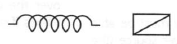 An
electromagnetic winding (or solenoid) is used to convert an electrical current
into a lateral movement. This can then be used to operate switches (as used in
relays) or other components such as fuel injectors or secondary air injection
solenoids.
An
electromagnetic winding (or solenoid) is used to convert an electrical current
into a lateral movement. This can then be used to operate switches (as used in
relays) or other components such as fuel injectors or secondary air injection
solenoids.
Fuse
 or
or
 A fuse is a device
which protects a circuit in the event of a fault. The fuse will 'blow' should a
short circuit occur, protecting that circuit from further damage. The number
next to the fuse on the circuit diagram indicates the position of the fuse in
the fusebox.
A fuse is a device
which protects a circuit in the event of a fault. The fuse will 'blow' should a
short circuit occur, protecting that circuit from further damage. The number
next to the fuse on the circuit diagram indicates the position of the fuse in
the fusebox.
Ground or Earth Point
 or
or
 This symbol is
used to show ground points. This is the negative connection to either the frame
or engine, and is a common cause of intermittent faults due to loose or corroded
connections.
This symbol is
used to show ground points. This is the negative connection to either the frame
or engine, and is a common cause of intermittent faults due to loose or corroded
connections.
Lamp or Bulb
 This
symbol is used to show all types of light bulbs. The numbers in the box relate
to the terminal numbers of the connector pins. An additional number outside the
box will identify the component.
This
symbol is used to show all types of light bulbs. The numbers in the box relate
to the terminal numbers of the connector pins. An additional number outside the
box will identify the component.
LED (Light Emitting Diode)
 Triumph
use LEDs for the alarm warning light, instrument illumination and warning
lights, gear change lights and rear light/brake lights on various models.
Triumph
use LEDs for the alarm warning light, instrument illumination and warning
lights, gear change lights and rear light/brake lights on various models.
Motor
 An
electric motor. This could be the starter motor or a motor within an actuator,
for example within the ABS modulator.
An
electric motor. This could be the starter motor or a motor within an actuator,
for example within the ABS modulator.
Relay
 A
relay is effectively an electromagnetic switch. To close the relay contacts and
complete the circuit, an electromagnet in the relay is energised which causes
the relay contacts to close, making the circuit complete.
A
relay is effectively an electromagnetic switch. To close the relay contacts and
complete the circuit, an electromagnet in the relay is energised which causes
the relay contacts to close, making the circuit complete.
Relays are used when the electrical current is too great for a mechanical switch, usually when the switching must be done quickly to prevent arcing across the switch contacts.
If a mechanical switch were used, the mechanical switch contacts would quickly burn away.
Resistor
 A
device placed in a cable to reduce a voltage or restrict the maximum current a
device can draw.
A
device placed in a cable to reduce a voltage or restrict the maximum current a
device can draw.
Splice
 A hard
cable joint where two or more cables are joined in the wiring harness. A
potential source of both open and short circuits.
A hard
cable joint where two or more cables are joined in the wiring harness. A
potential source of both open and short circuits.
Switches
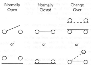
mechanical device for completing or breaking a circuit.
There are three common types of switch: Normally open, normally closed and change-over.
Tracing Circuits
The following is a description of two types of common electrical failures, and some of the methods which may be used to find them.
Open circuit
A break in an electrical circuit - current cannot flow.
Usually caused by a break in a wire or cable or by a loose connection. Open circuits can often by intermittent, making diagnosis difficult.
Short circuit
A 'short cut' in an electrical circuit - current by-passes the intended circuit, either to earth or to another, different circuit. Often caused by failure of the cable insulation due to chafing or trapping of the wire. There are two different types of short circuit - short to ground and short to Vbatt.
A short to ground means that the current is going to earth before it reaches the component it is supposed to feed.
These are often caused by chafing of the harness to the frame or wires trapped between a bolted component, and will often blow the fuse on that circuit.
A short to Vbatt is a short to battery voltage (12 Volts) and is caused by a live power supply wire contacting an adjacent cable. Note that it is also possible for a 5 Volt sensor reference voltage to short to an adjacent circuit, which can also cause electrical failures and DTCs (Diagnostic Trouble Code) to be stored.
When tracing a wire that is suspect, carefully check the circuit diagram before starting. Remember:
- wire may diverge at a splice and go off to feed other circuits. If these circuits are working, check for wiring faults from the splice onwards.
- the circuit diagram is not an accurate guide to the actual location of the parts when fitted on the bike. It is a schematic diagram of the circuits.
- particularly where engine management items are concerned, the circuit is only completed by the ECM. If the ECM is not connected, the circuit may register as open.
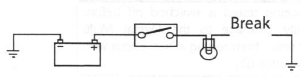
To Check Continuity:
Caution: Ensure the circuit being tested is switched off before measuring continuity. Damage to the Digital Multi Meter (DMM) may result from testing a 'live circuit with the meter set to resistance (Ω).
In the example below, the ground circuit continuity is being tested from the battery to the frame.
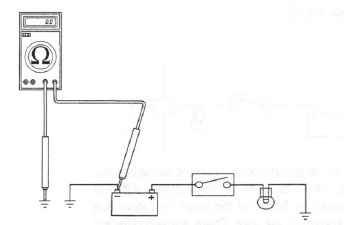
Continuity (resistance) Check
- Locate each end of the wire.
- Set the Digital Multi Meter (DMM) to resistance check (Ω).
- Probe each end of the wire.
- If there is continuity, the meter will usually bleep or register the resistance of the cable.
- A high resistance figure could indicate a dirty or corroded connection.
- If there is a break in the wire, the meter will not bleep or register a resistance.
- By probing the wire in various places, the position of a high resistance or break in the wire (open circuit) can be narrowed down until it is found.
To Measure Voltage:
In the example below, the circuit voltage is being measured at the bulb positive (+) terminal.
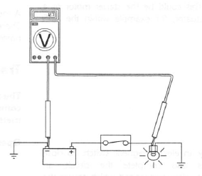
Voltage Check
- Turn the circuit to be tested ON
- Set the Digital Multi Meter (DMM) to Voltage check (V). Ensure the multi meter is set to dc volts for direct current circuits (most circuits) or ac volts for alternating current circuits (typically alternator output voltage tests).
- Set the range of the DMM to the range best suited to the voltage of the
circuit being tested (typically 20 volts for most DMMs).
Refer to the DMM manufacturers instructions. - Connect the black (ground) lead of the DMM to a reliable ground connection (usually the battery or frame ground).
- Locate the positive terminal of the wire or component to be tested.
- Connect the red (positive) lead of the DMM to the positive terminal.
- Read the voltage from meter.
Splices
Splices are probably the most common cause of wiring faults after connectors. Splices are made where two or more wires come together and diverge in different directions, usually to feed a different circuit.
To locate a splice, it is necessary to peel back the insulation and examine the splice for its integrity. The most common fault is where one of the wires at the joint has come adrift usually causing the circuit it feeds or earths to become 'dead'.
Switches
To check a switch, set the multimeter to resistance/ continuity and probe the two pins that form a closed circuit when the switch is pushed. If the switch is working correctly, the resistance should register or the meter will bleep.
Relays
All relay cases have a circuit path engraved on them showing the circuit path across the electromagnet and the switch. Before making any checks, first note the pin designations, current paths, and whether or not there is a diode in either circuit path.
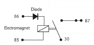
Make continuity checks across the electromagnet first, usually from pin 86 (positive) to pin 85 (negative). If a diode appears in the circuit use the diode check on the multimeter (volts scale) in the direction of current flow. If there is no diode, use the resistance check facility. An open circuit or unusually high resistance value indicates a faulty relay.
To check the switch side, apply a 12 volt supply between pins 86 and 85. With the supply connected the relay should be heard to click and there should be continuity between pins 30 and 87. An open circuit indicates a faulty relay.
CAN (Controller Area Networking)
CAN (sometimes called CANbus) is a protocol for data communication between Electronic Control Modules (ECMs). Each ECM on the network is connected by a single pair of twisted wires (or bus) which are used for the transmission of vehicle sensor data. By using CAN, the overall number of system sensors, and the amount of cabling required to allow ECMs to communicate with each other is greatly reduced.
This saves cost, weight and space, and makes the system more reliable, as the physical number of wires and connections is reduced.
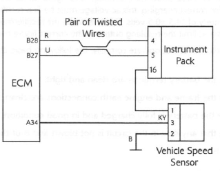
Extract from the circuit diagram showing CAN connection between ECMs
CAN works by each ECM sending out 'packets' of information (such as engine speed or fuel consumption information) on to the network bus (note that the network must be free of data before any ECM is allowed to transmit). This data is given a priority according to its importance (for example 'engine speed' may have a higher priority than 'low fuel level'), so that even if two ECMs send data at the same time, high priority information is always sent first. Lower priority data is then resent after the high priority data has been received by all ECMs on the network.
The receiving ECM confirms the data has been received correctly and that the data is valid, and this information is then used by the ECM as necessary. Specific data not required by an ECM will still be received and acknowledged as correct but then disregarded (for example if an ECM does not require 'clutch switch position' information, this data packet would be ignored).
This allows for a very high speed system of communication, which is also very reliable. Should one ECM fail or transmit corrupted or otherwise incorrect messages, none of the other ECMs on the network will be affected, and after a certain time that ECM will be prevented from transmitting further messages until the fault is rectified. This stops the ECM from clogging the network with incorrect data and preventing other messages from getting through. The fault would then be reported by a DTC (Diagnostic Trouble Code).
Triumph currently use CAN for communication between the engine ECM and the instruments.
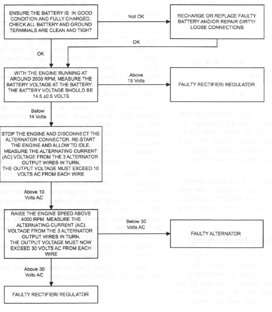
Alternator/Charging System
The charging system consists of an alternator and a rectifier/ regulator assembly and the battery. The alternator is made up of two parts, the stator, which is mounted to the crankcase or the engine cover, and the rotor, mounted to the end of the crankshaft. The stator is an assembly of 18 coils, arranged into 3 phases. The rotor is a series of magnets mounted in the engine flywheel, which are arranged so as to be positioned around the outside of the stator coils. As the engine rotates the alternator produces an ac (alternating current) voltage in each of the three phases of the alternator, typically of around 35 to 40 volts ac at 4000-5000 rpm, although this figure varies between models. As the battery requires dc (direct current) voltage for correct charging, this ac voltage must be first rectified to dc current, and then regulated to the correct voltage for the battery of 14.5 +-0.5 volts. This is done by the rectifier/regulator, which uses diodes to convert the alternator output to dc volts and limit the resulting output to the correct figure required for optimal battery charging.
If the charging circuit does not operate correctly, the following basic checks must be carried out before further diagnosis is performed:
- Check the battery terminals are clean and tight.
- Check the frame and engine earth connections are clean, tight and free from corrosion.
- Ensure the battery is fully charged and in good condition.
- Check that any fuse in the circuit is not blown and is of the correct rating.
Rectify any defects as necessary.
Diagnosis - Charging Circuit
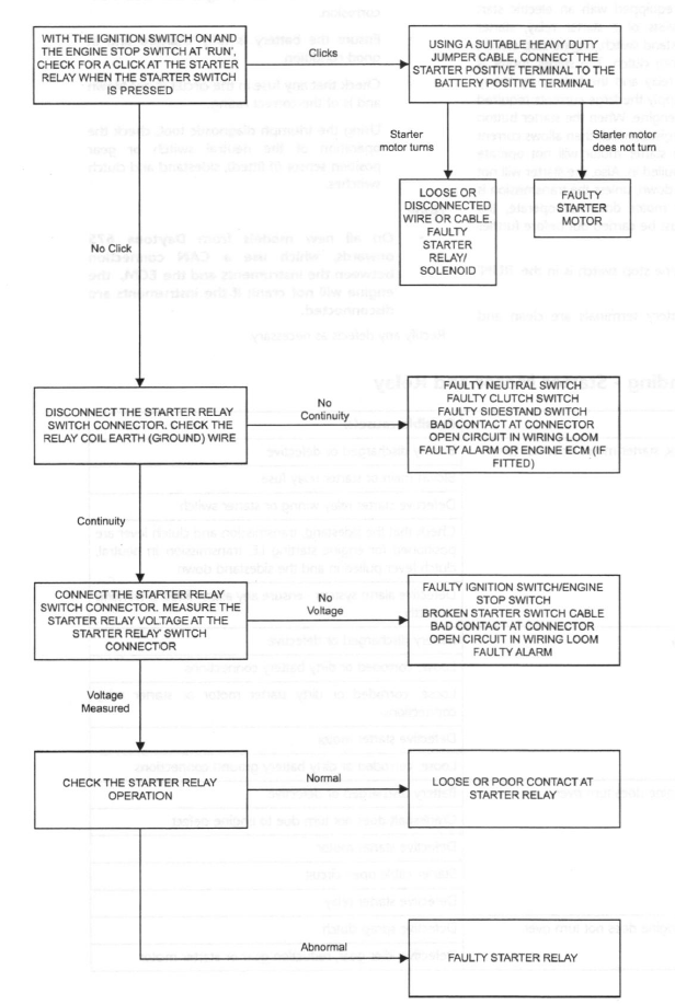
Starting Circuit
All Triumph models are equipped with an electric start system. This system consists of a starter relay, starter motor, starter switch, sidestand switch, engine stop switch, clutch switch and the sprag clutch. The starter motor is connected to the starter relay and the battery by heavy duty cables in order to supply the large currents required by the motor to start the engine. When the starter button is pressed the relay is energised, which then allows current to the starter motor. The starter motor will not operate unless the clutch lever is pulled in. Also, the starter will not operate if the sidestand is down, unless the transmission is in neutral. If the starter motor does not operate, the following basic checks must be carried out before further diagnosis is performed:
- Check the engine stop switch is in the 'RUN' position.
- Check the battery terminals are clean and tight.
- Check the frame and engine earth connections are clean, tight and free from corrosion.
- Ensure the battery is fully charged and in good condition.
- Check that any fuse in the circuit is not blown and is of the correct rating.
- Using the triumph diagnostic tool, check the operation of the neutral switch or gear position sensor (if fitted), sidestand and clutch switches.
Note:
- On all new models from Daytona 675 onwards, which use a CAN connection between the instruments and the ECM, the engine will not crank if the instruments are disconnected.
Rectify any defects as necessary.
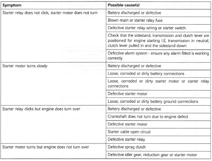
General Fault Finding - Starter Motor and Relay
Diagnosis - Starter Circuit
Inspection
Disassembled parts should be visually inspected and replaced with new ones if there are any signs of the following:
Abrasions, cracks, hardening, warping, bending, dents, scratches, colour changes, deterioration, seizure or damage of any nature.
Replacement Parts
Warning: Only Triumph genuine parts should be used to service, repair or convert Triumph motorcycles. To ensure that Triumph genuine parts are used, always order parts, accessories and conversions from an authorised Triumph dealer. The fitting of non-approved parts, accessories or conversions may adversely affect the handling, stability or other aspects of the motorcycle operation which may result in an accident causing serious injury or death.
Warning: Always have Triumph genuine parts, accessories and conversions fitted by an authorised Triumph dealer. The fitment of parts, accessories and conversions by a dealer who is not an authorised Triumph dealer may affect the handling, stability or other aspects of the motorcycle operation which may result in an accident causing serious injury or death.
Warning: Always have Triumph approved parts, accessories and conversions fitted by a trained technician. To ensure that a trained technician is used, have an authorised Triumph dealer fit the parts. The fitment of parts, accessories and conversions by personnel other than a trained technician at an authorised Triumph dealer may affect the handling, stability or other aspects of the motorcycle operation which may result in an accident causing serious injury or death.
Service Data
The service data listed in this manual gives dimensions and specifications for brand new, original parts. Where it is permissible to allow a part to exceed these figures, then the service limit is given.
The terms of the motorcycle warranty will be invalidated by the fitting of other than genuine Triumph parts.
All genuine Triumph parts have the full backing of the motorcycle warranty. Triumph dealers are obliged to supply only genuine Triumph recommended parts.
Specification
Triumph are constantly seeking to improve the specification, design and production of their motorcycles and alterations take place accordingly.
While every effort has been made to ensure the accuracy of this Manual, it should not be regarded as an infallible guide to current specifications of any particular motorcycle.
Authorised Triumph dealers are not agents of Triumph and have no authority to bind the manufacturer by any expressed or implied undertaking or representation.
See also:
 Triumph Street Triple S - Service manual > Safety Instructions
Jacking and Lifting Warning: Always ensure that any lifting apparatus has adequate load and safety capacity for the weight to be lifted. Ensure the motorcycle is well supported to prevent any possibility of the machine falling during lifting or jacking, or while repairs and servicing are carried out.
Triumph Street Triple S - Service manual > Service Tools and Garage Equipment
Special service tools have been developed to facilitate removal, dismantling and assembly of certain mechanical components in a practical manner without causing damage. Some operations in this Service Manual cannot be carried out without the aid of the relevant service tools. Where this is the case, the tools required will be described during the procedure.
 Benelli Imperiale 400
 BMW F900XR
 Honda CB500X
 KTM 390 Adventure
 Triumph Street Triple S
 Yamaha MT-03
 Kawasaki Z400
 Triumph Street Triple S
 Yamaha MT-03