 Kawasaki Z400 - Service manual > DFI System
Fuel System (DFI) / DFI System
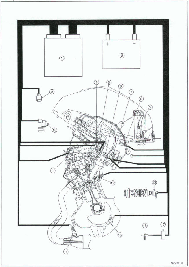
- ECU
- Battery
- Vehicle-down Sensor
- Intake Air Pressure Sensor
- Idle Speed Control Valve Actuator
- Throttle Sensor
- Fuel Injectors
- Intake Air Temperature Sensor
- Fuel Pump
- Purge Valve (Equipped Models)
- Air Switching Valve
- Water Temperature Sensor
- Gear Position Sensor
- Oxygen Sensor
- Crankshaft Sensor
- Rear Wheel Rotation Sensor
- ABS Hydraulic Unit (ABS Equipped Models)
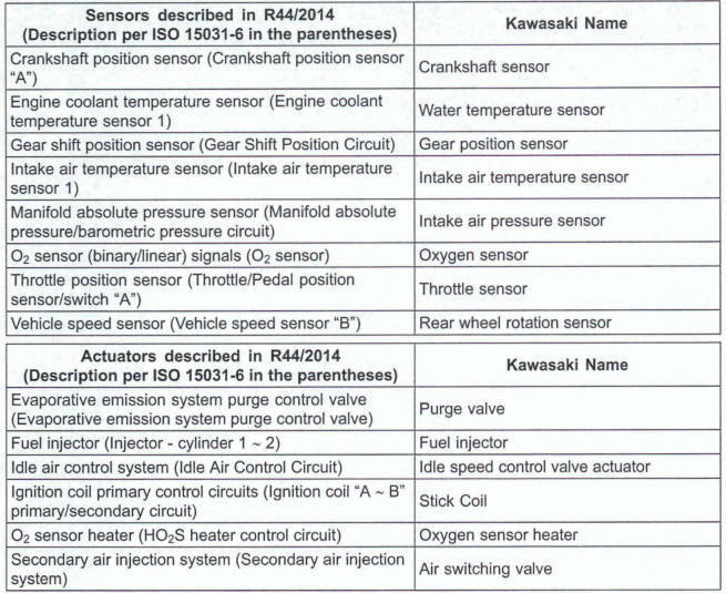
DFI Components Naming
The terms used in the European regulation for DFI components are sometimes different from those used by Kawasaki. Use this table to cross reference terms which my appear in a generic scan tool when diagnosing the DFI system.
This page Intentionally left blank
DFI System Wiring Diagram
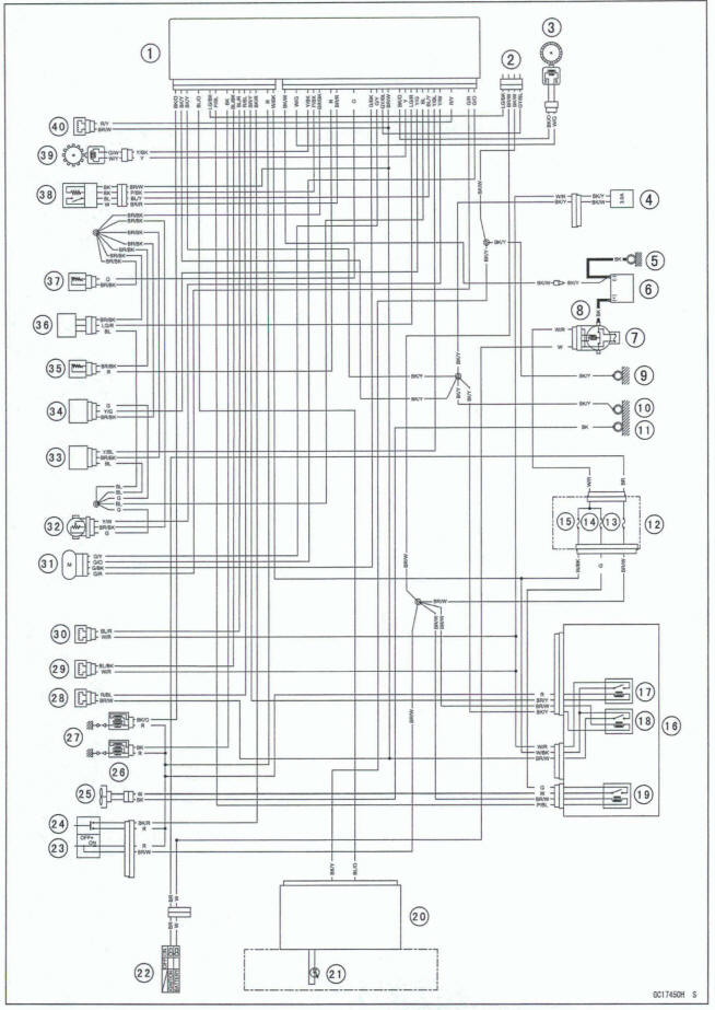
Part Names
- ECU
- Kawasaki Diagnostic System Connector
- Rear Wheel Rotation Sensor
- Fuel Pump
- Engine Ground
- Battery
- Main Fuse 30 A
- Starter Relay
- Frame Ground (4)
- Frame Ground (2)
- Frame Ground (1 )
- Fuse Box (1)
- Ignition Fuse 10 A .
- Fan Fuse 15 A
- ECU Fuse 15 A
- Relay Box
- Fuel Pump Relay
- ECU Main Relay
- Radiator Fan Relay
- Meter Unit
- Yellow Engine Warning Indicator Light (LED)
- Ignition Switch
- Engine Stop Switch
- Starter Button
- Fan Motor
- Stick Coils
- Spark Plugs
- Air Switching Valve
- Fuel Injector #I
- Fuel Injector #2
- Idle Speed Control Valve Actuator
- Throttle Sensor
- Intake Air Pressure Sensor
- Vehicle-down Sensor
- Intake Air Temperature Sensor
- Gear Position Sensor
- Water Temperature Sensor
- Oxygen Sensor
- Crankshaft Sensor
- Purge Valve (Equipped Models)
DFI System Wiring Diagram (ABS Equipped Models)
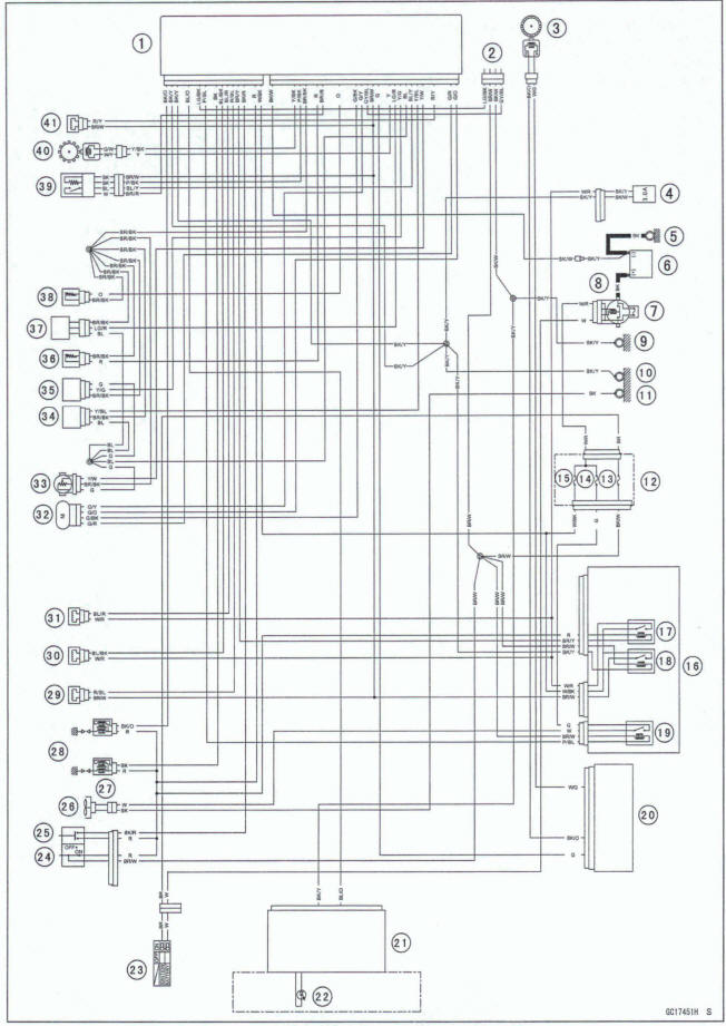
Part Names
ECU
- Kawasaki Diagnostic System Connector
- Rear Wheel Rotation Sensor
- Fuel Pump
- Engine Ground
- Battery
- Main Fuse 30 A
- Starter Relay
- Frame Ground (4)
- Frame Ground (2)
- Frame Ground (1 )
- Fuse Box (1)
- Ignition Fuse I0 A
- Fan Fuse 15 A
- ECU Fuse 15 A
- Relay Box
- Fuel Pump Relay
- ECU Main Relay
- Radiator Fan Relay
- ABS Hydraulic Unit
- Meter Unit
- Yellow Engine Warning Indicator Light (LED)
- Ignition Switch
- Engine Stop switch
- Starter Button
- Fan Motor
- Stick Coils
- Spark Plugs
- Air Switching Valve
- Fuel Injector #I
- Fuel Injector #2
- Idle Speed Control Valve Actuator
- Throttle Sensor
- Intake Air Pressure Sensor
- Vehicle-down Sensor
- Intake Air Temperature Sensor
- Gear Position Sensor
- Water Tmp6fature Sensor
- Oxygen sensor
- Crankshaft sensor
- Purge Valve (Equipped Models)
Color Codes:
BK: Black
GY: Gray
PU: Purple
BL: Blue
LB: Light Blue
R: Red
BR: Brown
G: Green
LO: Light Green
V: Violet
CH: Chocolate
0: Orange
W: White
DG: Dark Green
P: Pink
Y: Yellow
Terminal Numbers of ECU Connectors
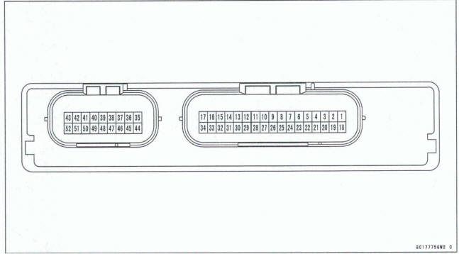
Terminal Names
- ldle Speed Control Valve Actuator: GI0
- ldle Speed Control Valve Actuator: GIR
- Unused
- Green Neutral Indicator Light (LED): LG
- Purge Valve (Equipped Models): WY
- Unused
- Throttle Sensor: YMI
- Intake Air Pressure Sensor: YBL
- Oxygen Sensor: BW
- Power Supply to Sensors: BL
- Vehicle-down Sensor: YIG
- Gear Position Sensor: LGIR
- Crankshaft Sensor (+): Y
- Power Supply to Rear Wheel Rotation Sensor (EX400H): BKIO
- Rear Wheel Rotation Sensor Signal (from ABS Hydraulic Unit, EX400GlJ): G
- Power Supply to ECU (from ECU Main Relay): BW
- External Communication Line (Kawasaki Diagnostic System): GYIBL
- ldle Speed Control Valve Actuator: GN
- ldle Speed Control Valve Actuator: G/BK
- Unused
- Unused
- Water Temperature Sensor: 0
- Unused
- Unused
- Oxygen Sensor: BR/R
- Intake Air Temperature Sensor: R
- Unused
- Ground for Sensors: BR/BK
- Oxygen Sensor Heater: PIBK
- Crankshaft Sensor (-): Y/BK
- Rear Wheel Rotation Sensor Output: LGNV
- Rear Wheel Rotation Sensor (EX400H): WIG
- Unused
- Ground for Control System: BW
- Power Supply to ECU (from Battery): W/BK
- Engine Stop Switch: R
- Starter Lockout Switch: RIG
- Starter Button: BWR
- Fuel Pump Relay: BRN
- Air Switching Valve: FUBL
- Fuel Injector #2: BUR
- Fuel Injector #I: BUBK
- Stick Coil #I : BK
- Side Stand Switch: GIBK
- Radiator Fan Relay: PIBL
- External Communication Line (Kawasaki Diagnostic System): LG/BK
- Meter Unit (Tachometer): LB
- Meter Communication Line: BUO
- Unused
- Ground for Fuel System: BW
- Ground for Ignition System: BW
- Stick Coil #2: BK/O
See also:
 Kawasaki Z400 - Service manual > Fuel System (DFI)
Exploded View
Kawasaki Z400 - Service manual > DFI Parts Location
Battery [A] Kawasaki Diagnostic System Connector [B] ECU [A] Relay Box [B]
 Benelli Imperiale 400
 BMW F900XR
 Honda CB500X
 KTM 390 Adventure
 Triumph Street Triple S
 Yamaha MT-03
 Kawasaki Z400
 Triumph Street Triple S
 Yamaha MT-03