 Yamaha MT-03 - Service manual > Cylinder and piston
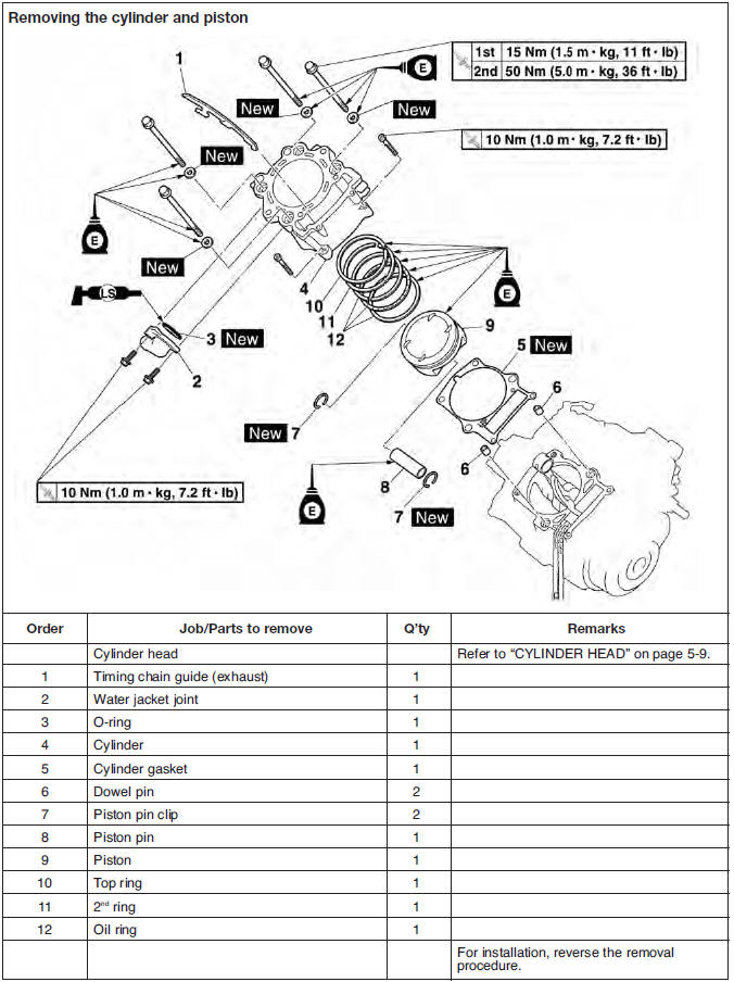
Removing the cylinder and piston
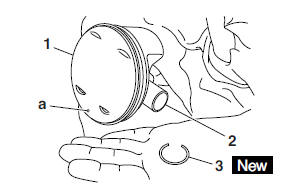
1. Remove:
- Piston pin clips "1"
- Piston pin "2"
- Piston "3"
CAUTION:
Do not use a hammer to drive the piston pin out.
NOTE:
- Before removing the piston pin clip, cover the crankcase opening with a clean rag to prevent the piston pin clip from falling into the crankcase.
- Before removing the piston pin, deburr the piston pin clip's groove and the piston's pin bore area. If both areas are deburred and the piston pin is still difficult to remove, remove it with the piston pin puller set "4".
 Piston pin puller set
90890-01304
Piston pin puller set
90890-01304
2. Remove:
- Top ring
- 2nd ring
- Oil ring
NOTE:
When removing a piston ring, open the end gap with your fingers and lift the other side of the ring over the piston crown.
Checking the cylinder and piston
1. Check:
- Piston wall
- Cylinder wall
Vertical scratches → Replace the cylinder and the piston and piston rings as a set.
2. Measure:
- Piston-to-cylinder clearance
a. Measure cylinder bore "C" with the cylinder bore gauge.
NOTE:
Measure cylinder bore "C" by taking side-toside and front-to-back measurements of the cylinder. Then, find the average of the measurements.
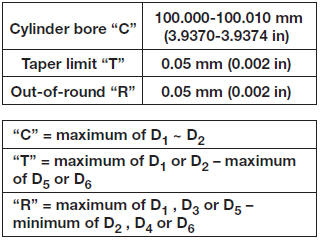
b. If out of specification, replace the cylinder and the piston and piston rings as a set.
c. Measure piston skirt diameter "P" with the micrometer.
a. 10 mm (0.39 in) from the bottom edge of the piston
d. If out of specification, replace the piston and piston rings as a set.
e. Calculate the piston-to-cylinder clearance with the following formula.
Piston-to-cylinder clearance = Cylinder bore "C" - Piston skirt diameter "P"
 Piston-to-cylinder clearance
0.030-0.055 mm
(0.0012-0.0022 in)
<Limit>: 0.13 mm (0.0051 in)
Piston-to-cylinder clearance
0.030-0.055 mm
(0.0012-0.0022 in)
<Limit>: 0.13 mm (0.0051 in)
f. If out of specification, replace the cylinder and the piston and piston rings as a set.
Checking the piston rings
1. Measure:
- Piston ring side clearance
Out of specification → Replace the piston and piston rings as a set.
NOTE:
Before measuring the piston ring side clearance, eliminate any carbon deposits from the piston ring grooves and piston rings.
 Piston ring side clearance
Top ring
0.030-0.080 mm (0.0012-0.0031 in) <Limit>: 0.13 mm (0.0051 in)
2nd ring
0.030-0.070 mm (0.0012-0.0028 in) <Limit>: 0.11 mm (0.0043 in)
2. Install:
- Piston ring (into the cylinder)
NOTE:
Level the piston ring into the cylinder with the piston crown.
a. 40 mm (1.57 in)
3. Measure:
- Piston ring end gap
Out of specification → Replace the piston ring.
NOTE:
The oil ring expander spacer's end gap cannot be measured. If the oil ring rail's gap is excessive, replace all three piston rings.
 Piston ring end gap
Top ring
0.20-0.35 mm (0.0079-0.0138 in) <Limit>: 0.60 mm (0.0236 in)
2nd ring
0.35-0.50 mm (0.0138-0.0197 in) <Limit>: 0.85 mm (0.0335 in)
Oil ring
0.20-0.70 mm (0.0079-0.0276 in)
Checking the piston pin
1. Check:
- Piston pin
Blue discoloration/grooves → Replace the piston pin, and then check the lubrication system.
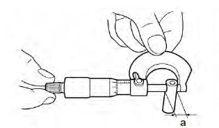
2. Measure:
- Piston pin outside diameter "a"
Out of specification → Replace the piston pin.
 Piston pin outside diameter
22.991-23.000 mm
(0.9052-0.9055 in)
<Limit>: 22.971 mm (0.9044 in)
Piston pin outside diameter
22.991-23.000 mm
(0.9052-0.9055 in)
<Limit>: 22.971 mm (0.9044 in)
3. Measure:
- Piston pin bore inside diameter "b"
Out of specification → Replace the piston
 Piston pin bore inside
diameter
23.004-23.015 mm
(0.9057-0.9061 in)
<Limit>: 23.045 mm (0.9073 in)
Piston pin bore inside
diameter
23.004-23.015 mm
(0.9057-0.9061 in)
<Limit>: 23.045 mm (0.9073 in)
4. Calculate:
- Piston-pin-to-piston-pin-bore clearance
Out of specification → Replace the piston pin and piston as a set.
Piston-pin-to-piston-pin-bore clearance = Piston pin bore inside diameter "b" - Piston pin outside diameter "a"
 Piston-pin-to-piston clearance
0.004-0.024 mm
(0.0002-0.0009 in)
<Limit>: 0.074 mm (0.0029 in)
Piston-pin-to-piston clearance
0.004-0.024 mm
(0.0002-0.0009 in)
<Limit>: 0.074 mm (0.0029 in)
Installing the piston and cylinder
1. Install:
- Top ring "1"
- 2nd ring "2"
- Oil ring expander "3"
- Lower oil ring rail "4"
- Upper oil ring rail "5"
NOTE:
Be sure to install the piston rings so that the manufacturer's marks or numbers face up.
2. Install:
- Piston "1"
- Piston pin "2"
- Piston pin clips "3"

NOTE:
- Apply engine oil to the piston pin.
- Make sure the punch mark a on the piston points towards the exhaust side of the cylinder.
- Before installing the piston pin clips, cover the crankcase opening with a clean rag to prevent the clip from falling into the crankcase.
3. Install:
- Cylinder gasket

- Dowel pins
4. Lubricate:
- Piston
- Piston rings
- Cylinder (with the recommended lubricant)
 Recommended lubricant
Engine oil
Recommended lubricant
Engine oil
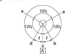
5. Offset:
- piston ring end gaps
a. Top ring
b. Upper oil ring rail
c. Oil ring expander
d. Lower oil ring rail
e. 2nd ring
f. 20 mm (0.79 in)
 Exhaust side
6. Install:
- Cylinder "1"
- Timing chain guide (exhaust)
NOTE:
- While compressing the piston rings with one hand, install the cylinder with the other hand.
- Pass the timing chain and timing chain guide (exhaust side) through the timing chain cavity.
7. Install:
- Washers

- Cylinder bolts
NOTE:
- Lubricate the cylinder bolt threads and muting surface with engine oil.
- Install the washers with their blunt surface facing up.
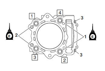
8. Tighten:
- Cylinder bolts
 Cylinder bolts "1"
L = 116 mm (4.57 in) 1st 15 Nm (1.5 m*kg, 11 ft*lb) 2nd 50 Nm (5.0 m*kg, 36 ft*lb)
Cylinder bolts "2"
L = 109 mm (4.29 in) 1st 15 Nm (1.5 m*kg, 11 ft*lb) 2nd 50 Nm (5.0 m*kg, 36 ft*lb)
Cylinder bolts
(timing chain side) "3" 10 Nm (1.0 m*kg, 7.2 ft*lb)
NOTE:
Tighten the cylinder bolts in the proper tightening sequence as shown and torque them in two stages.
See also:
 Yamaha MT-03 - Service manual > Valves and valve springs
Removing the valves The following procedure applies to all of the valves and related components.
 Benelli Imperiale 400
 BMW F900XR
 Honda CB500X
 KTM 390 Adventure
 Triumph Street Triple S
 Yamaha MT-03
 Kawasaki Z400
 Triumph Street Triple S
 Yamaha MT-03