 Yamaha MT-03 - Service manual > Clutch
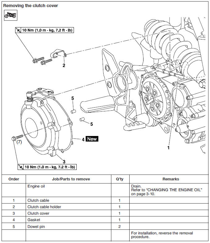
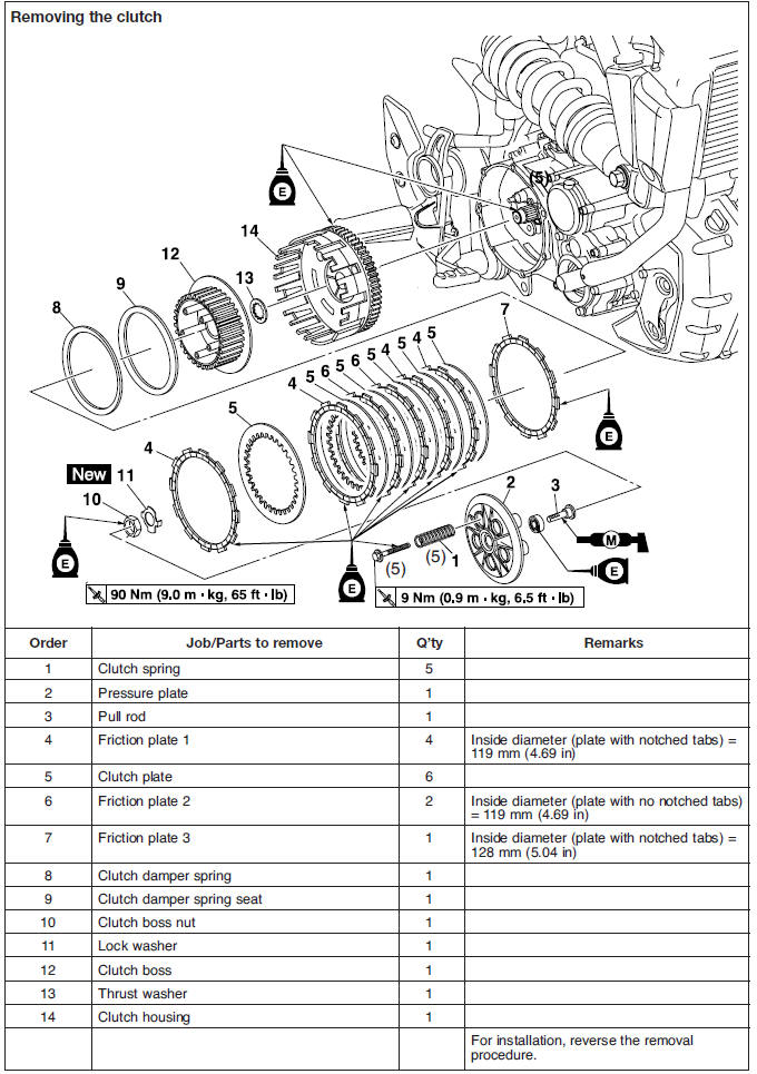
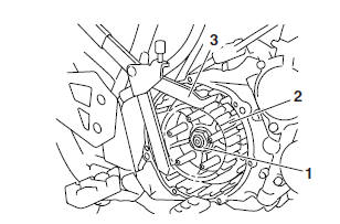
Removing the clutch
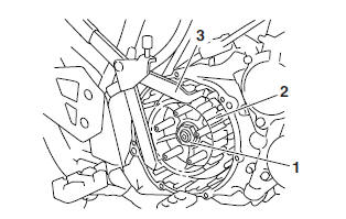
1. Remove:
- Clutch cover "1"
NOTE:
Loosen each bolt 1/4 of a turn at a time, in stages and in a crisscross pattern. After all of the bolts are fully loosened, remove them.
2. Straighten the lock washer tab.
3. Loosen:
- Clutch boss nut "1"
NOTE:
While holding the clutch boss "2" with the universal clutch holder "3", loosen the clutch boss nut.
 Universal clutch holder
90890-04086
Universal clutch holder
90890-04086
4. Remove:
- Clutch boss nut
- Lock washer
- Clutch boss
Checking the friction plates
The following procedure applies to all of the friction plates.
1. Check:
- Friction plate "1"
- Friction plate "2"
- Friction plate "3"
Damage/wear → Replace the friction plates as a set.
2. Measure:
- Friction plate 1 thickness
- Friction plate 2 thickness
- Friction plate 3 thickness
Out of specification → Replace the friction plates as a set.
NOTE:
Measure the friction plate at four places.
 Friction plate 1 thickness
2.90-3.10 mm (0.114-0.122 in)
<Limit>: 2.80 mm (0.110 in)
Friction plate 1 thickness
2.90-3.10 mm (0.114-0.122 in)
<Limit>: 2.80 mm (0.110 in)
Friction plate 2 thickness 2.92-3.08 mm (0.115-0.121 in) <Limit>: 2.80 mm (0.110 in)
Friction plate 3 thickness 2.90-3.10 mm (0.114-0.122 in) <Limit>: 2.80 mm (0.110 in)
Checking the clutch plates
The following procedure applies to all of the clutch plates.
1. Check:
- Clutch plate
Damage → Replace the clutch plates as a set.
2. Measure:
- Clutch plate warpage.
(with a surface plate and thickness gauge "1") Out of specification → Replace the clutch plates as a set.
 Clutch plate warpage limit
0.20 mm (0.0079 in)
Clutch plate warpage limit
0.20 mm (0.0079 in)
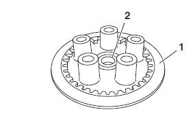
Checking the clutch springs
The following procedure applies to all of the clutch springs.
1. Check:
- Clutch spring
Damage → Replace the clutch springs as a set.
2. Measure:
- Clutch spring free length "a"
Out of specification → Replace the clutch springs as a set.
 Clutch spring free length
55.6 mm (2.19 in)
<Limit>: 52.82 mm (2.08 in)
Clutch spring free length
55.6 mm (2.19 in)
<Limit>: 52.82 mm (2.08 in)
Checking the clutch housing
1. Check:
- Clutch housing dogs
Damage/pitting/wear → Deburr the clutch housing dogs or replace the clutch housing.
NOTE:
Pitting on the clutch housing dogs will cause erratic clutch operation.
Checking the clutch boss
The following procedure applies to all of the clutch springs.
1. Check:
- Clutch boss splines
Damage/pitting/wear → Replace the clutch boss.
NOTE:
Pitting on the clutch boss splines will cause erratic clutch operation.
Checking the pressure plate
1. Check:
- Pressure plate "1"
Cracks/damage → Replace.
- Bearing "2"
Damage/wear → Replace.
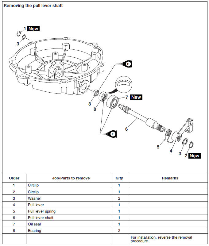
Checking the pull lever shaft and pull rod
1. Check:
- Pull lever shaft pinion gear teeth "1"
- Pull rod teeth "2"
Damage/wear → Replace the pull rod and pull lever shaft pinion gear as a set.
2. Check:
- Pull rod bearing
Damage/wear → Replace.
Checking the primary driven gear
1. Check:
- Primary driven gear
Damage/wear → Replace the primary drive gear and clutch housing as a set.
Excessive noise during operation → Replace the primary drive gear and clutch housing as a set.
Installing the clutch
1. Install:
- Clutch boss
- Lock washer

- Clutch boss nut "1"
NOTE:
Lubricate the crankshaft end threads with engine oil.
2. Tighten:
- Clutch boss nut
 Clutch boss nut
90 Nm (9.0 m*kg, 65 ft*lb)
Clutch boss nut
90 Nm (9.0 m*kg, 65 ft*lb)
NOTE:
While holding the clutch boss "2" with the universal clutch holder "3", tighten the clutch boss nut.
 Universal clutch holder
90890-04086
Universal clutch holder
90890-04086
3. Bend the lock washer tab along a flat side of the nut.
4. Lubricate:
- Friction plates
- Clutch plates (with the recommended lubricant)
 Recommended lubricant
Engine oil
Recommended lubricant
Engine oil
5. Install:
- Clutch damper spring seat "1"
- Clutch damper spring "2"
- Friction plate 3 "3"
- Clutch plates "4"
- Friction plates 1 "5", "7"
- Friction plates 2 "6"
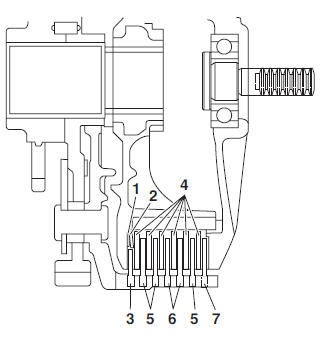
NOTE:
- Install the clutch damper spring "2" with the "OUTSIDE" mark facing out.
- First, install a friction plate and then alternate between a clutch plate and a friction plate.
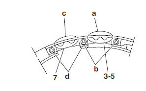
- Install friction plate 3 "3" and friction plate 1 "5" so that the tab with two notches "a" is between the two punch marks "b" on the clutch housing as shown.
- Install friction plate 1 "7" so that the tab with two notches "c" is between the two punch marks "d" on the clutch housing as shown.
6. Install:
- Clutch springs
- Clutch spring bolts
 Clutch spring bolts
9 Nm (0.9 m*kg, 6.5 ft*lb)
Clutch spring bolts
9 Nm (0.9 m*kg, 6.5 ft*lb)
NOTE:
- Lubricate the clutch spring threads with engine oil.
- Tighten the clutch spring bolts in stages and in a crisscross pattern.
7. Install:
- Dowel pins
- Gasket
- Clutch cover
 Clutch cover bolts
10 Nm (1.0 m*kg, 7.2 ft*lb)
Clutch cover bolts
10 Nm (1.0 m*kg, 7.2 ft*lb)
- Clutch cable holder
 Clutch cable holder bolts
10 Nm (1.0 m*kg, 7.2 ft*lb)
Clutch cable holder bolts
10 Nm (1.0 m*kg, 7.2 ft*lb)
NOTE:
- To install the clutch cover, position the pull rod so that the teeth face towards that rear of the motorcycle.
- Tighten the clutch cover bolts in stages and in a crisscross pattern.
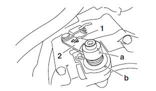
8. Install:
- Pull lever spring "1"
- Pull lever "2"
- Washer
- Circlip

NOTE:
- Install the pull lever with the "UP" mark facing up.
- Align the punch mark "a" on the pull lever with the punch mark "b" on the clutch cover.
- Install the pull lever spring "1" as shown.
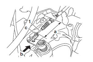
9. Install:
- Clutch cable "1"
10.Check:
- Clutch cable length "a" Out of specification →Adjust.
NOTE:
- Push the pull lever in direction "b" and check the cable length "a".
- Bend the tab "c" on the pull lever to secure the clutch cable.
 Clutch cable length
65.6-73.9 mm (2.58-2.91 in)
Clutch cable length
65.6-73.9 mm (2.58-2.91 in)
11.Adjust:
- Clutch cable length
NOTE:
Move the pull lever a notch until the cable length is within specification.
12.Adjust:
- Clutch cable free play
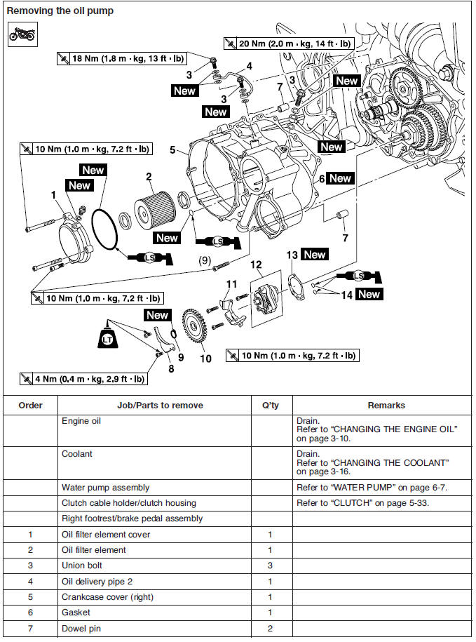
Oil pump
Checking the oil pump
1. Check:
- Oil pump driven gear "1"
- Oil pump housing 1 "2"
- Oil pump housing cover "3"
- Oil pump housing 2 "4" Cracks/damage/wear → Replace the defective part(s).
2. Measure:
- Inner-rotor-to-outer-rotor-tip clearance "a"
- Outer-rotor-to-oil-pump-housing clearance "b"
- Oil-pump-housing-to-inner-rotor-and-outerrotor clearance "c" Out of specification → Replace the oil pump.
1. Inner rotor
2. Outer rotor
3. Oil pump housing
 Inner-rotor-to-outer-rotor-tip
clearance
0.07-0.12 mm
(0.0028-0.0047 in)
<Limit>: 0.2 mm (0.008 in)
Outer-rotor-to-oil-pump-housing
clearance
0.03-0.08 mm
(0.0012-0.0031 in)
<Limit>: 0.15 mm (0.0059 in)
Oil-pump-housing-to-innerrotor-
and-outer-rotor clearance
0.03-0.08 mm
(0.0012-0.0031 in)
<Limit>: 0.15 mm (0.0059 in)
Inner-rotor-to-outer-rotor-tip
clearance
0.07-0.12 mm
(0.0028-0.0047 in)
<Limit>: 0.2 mm (0.008 in)
Outer-rotor-to-oil-pump-housing
clearance
0.03-0.08 mm
(0.0012-0.0031 in)
<Limit>: 0.15 mm (0.0059 in)
Oil-pump-housing-to-innerrotor-
and-outer-rotor clearance
0.03-0.08 mm
(0.0012-0.0031 in)
<Limit>: 0.15 mm (0.0059 in)
3. Check:
- Oil pump operation
Rough movement → Repeat steps (1) and (2) or replace the defective part(s).
Checking the oil delivery pipes and hoses
The following procedure applies to all of the oil delivery pipes and hoses.
1. Check:
- Oil delivery pipe
- Oil delivery hose
Damage → Replace.
Obstruction →Wash and blow out with compressed air.
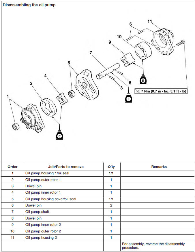
Assembling the oil pump
1. Lubricate:
- Oil pump inner rotor 1
- Oil pump inner rotor 2
- Oil pump outer rotor 1
- Oil pump outer rotor 2
- Oil pump shaft (with the recommended lubricant)
 Recommended lubricant
Engine oil
Recommended lubricant
Engine oil
2. Install:
- Oil pump outer rotor 2 "1"
- Oil pump inner rotor 2 "2" (to the oil pump housing 2)
- Oil pump housing
 Oil pump housing bolts
7 Nm (0.7 m*kg, 5.1 ft*lb)
Oil pump housing bolts
7 Nm (0.7 m*kg, 5.1 ft*lb)
NOTE:
- Install oil pump inner rotor 2 and outer rotor 2 with the alignment marks "a" facing up.
- When installing the inner rotor, align the pin in the oil pump shaft with the groove in the inner rotor.
3. Check:
- Oil pump operation
Refer to "CHECKING THE OIL PUMP".
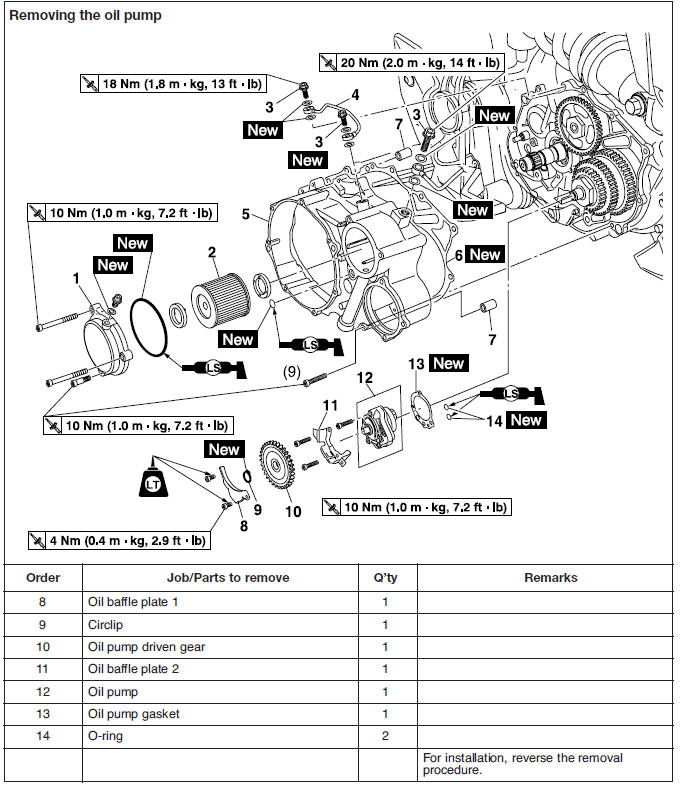
Installing the oil pump
1. Install:
- Oil pump gasket

- Oil pump
- Oil baffle plate 2
 Oil baffle plate 2 bolts
10 Nm (1.0 m*kg, 7.2 ft*lb)
Oil baffle plate 2 bolts
10 Nm (1.0 m*kg, 7.2 ft*lb)
- Oil pump driven gear "1"
- Oil pump driven gear circlip

- Oil baffle plate 1
 Oil baffle plate 1 bolts
4 Nm (0.4 m*kg, 2.9 ft*lb)
LOCTITE
Oil baffle plate 1 bolts
4 Nm (0.4 m*kg, 2.9 ft*lb)
LOCTITE
CAUTION:
After tightening the bolts, make sure the oil pump turns smoothly.
NOTE:
- Install the oil pump driven gear "1" in the direction shown.
- Install the circlip with its blunt surface facing the engine.
Balancer driven gear
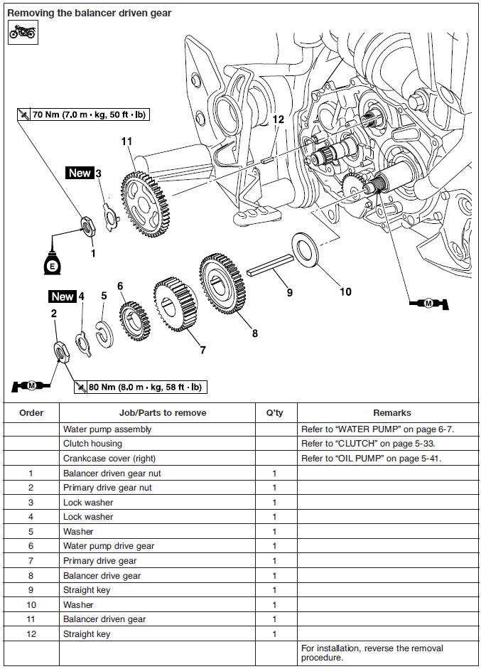
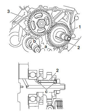
Removing the balancer driven gear and Balancer drive gear
1. Straighten the lock washer tab.
2. Loosen:
- Balancer driven gear nut "1"
- Primary drive gear nut "2"
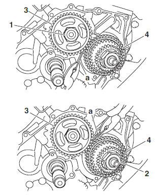
NOTE:
Place an aluminum plate "a" between the teeth of the balancer driven gear "3" and balancer drive gear "4".
3. Remove:
- Balancer driven gear
- Water pump drive gear
- Primary drive gear
- Balancer drive gear
Checking the balancer driven gear, water pump Drive gear, primary drive gear, and balancer Drive gear
1. Check:
- Balancer driven gear
- Balancer drive gear
- Water pump drive gear
- Primary drive gear
Damage/wear → Replace.
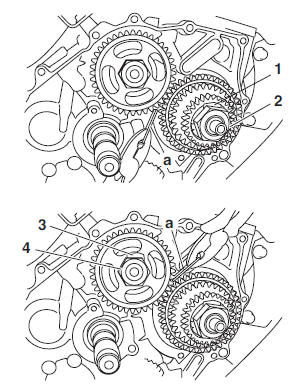
Installing the balancer driven gear and Balancer drive gear
1. Install:
- Washer
- Balancer drive gear "1"
- Straight key "2"
- Balancer driven gear "3"
- Straight key
- Primary drive gear
- Water pump drive gear
NOTE:
- Align the punch mark "a" on the balancer drive gear with the punch mark "b" on the balancer driven gear.
- Install the key with its blunt surface facing "c" the crankshaft.
2. Install:
- Lock washer "1"

- Primary drive gear nut "2"
 Primary drive gear nut
80 Nm (8.0 m*kg, 58 ft*lb)
Primary drive gear nut
80 Nm (8.0 m*kg, 58 ft*lb)
- Lock washer "3"
- Balancer driven gear nut "4"
 Balancer driven gear nut
70 Nm (7.0 m*kg, 50 ft*lb)
Balancer driven gear nut
70 Nm (7.0 m*kg, 50 ft*lb)
NOTE:
Place an aluminum plate "a" between the teeth of the balancer drive gear and balancer driven gear
3. Bend the lock washer tab.
Shift shaft
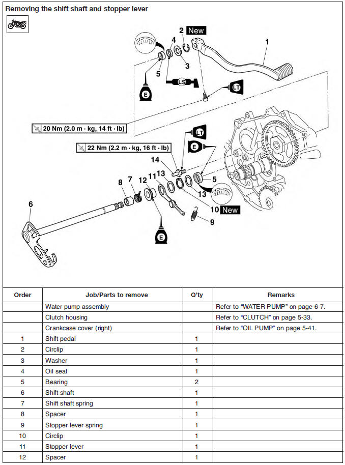
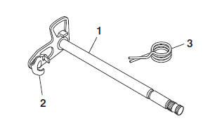
Checking the shift shaft
1. Check:
- Shift shaft "1"
- Shift shaft pawl "2" Bends/damage/wear → Replace.
- Shift shaft spring "3" Damage/wear → Replace.
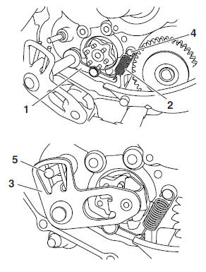
Checking the stopper lever
1. Check:
- Stopper lever "1"
Bends/damage → Replace.
Roller turns roughly → Replace the stopper lever.
- Stopper lever spring "2" Damage/wear → Replace.
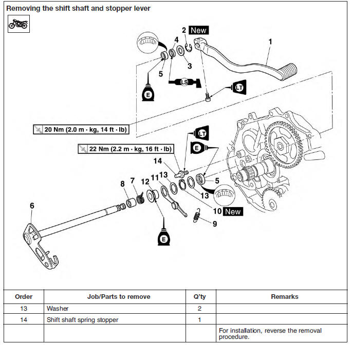
Installing the shift shaft
1. Install:
- Shift shaft spring stopper
 Shift shaft spring stopper
22 Nm (2.2 m*kg, 16 ft*lb)
LOCTITE
Shift shaft spring stopper
22 Nm (2.2 m*kg, 16 ft*lb)
LOCTITE
2. Install:
- Stopper lever "1"
- Stopper lever spring "2"
- Shift shaft "3"
NOTE:
- Hook the ends of the stopper lever spring onto the stopper lever and the crankcase boss "4".
- Mesh the stopper lever with the shift drum segment assembly.
- Lubricate the oil seal lips with lithium-soapbased grease.
- Hook the end of the shift shaft spring onto the shift shaft spring stopper "5".
3. Install:
- Shift pedal
 Shift pedal bolt
20 Nm (2.0 m*kg, 14 ft*lb)
LOCTITE 243
Shift pedal bolt
20 Nm (2.0 m*kg, 14 ft*lb)
LOCTITE 243
See also:
 Yamaha MT-03 - Service manual > Cylinder and piston
Removing the cylinder and piston 1. Remove: Piston pin clips "1" Piston pin "2" Piston "3"
 Benelli Imperiale 400
 BMW F900XR
 Honda CB500X
 KTM 390 Adventure
 Triumph Street Triple S
 Yamaha MT-03
 Kawasaki Z400
 Triumph Street Triple S
 Yamaha MT-03