 Kawasaki Z400 - Service manual > Crankshaft/Transmission
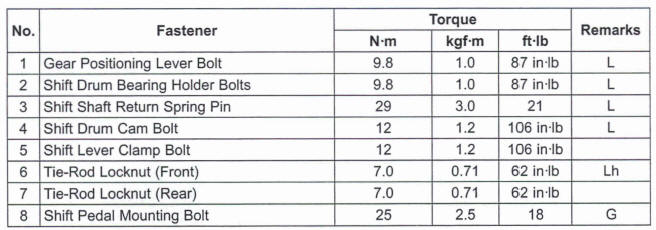
Exploded View

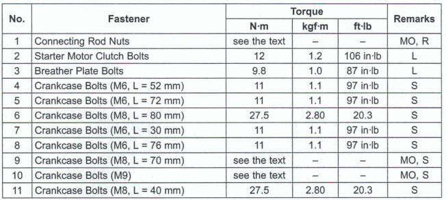
G: Apply grease.
L: Apply a non-permanent locking agent.
LG: Apply liquid gasket.
M: Apply molybdenum disulfide grease.
MO: Apply molybdenum disulfide oil solution.
(mixture of the engine oil and molybdenum disulfide grease in a weight ratio 10:l)
R: Replacement Parts
S: Follow the specified tightening sequence
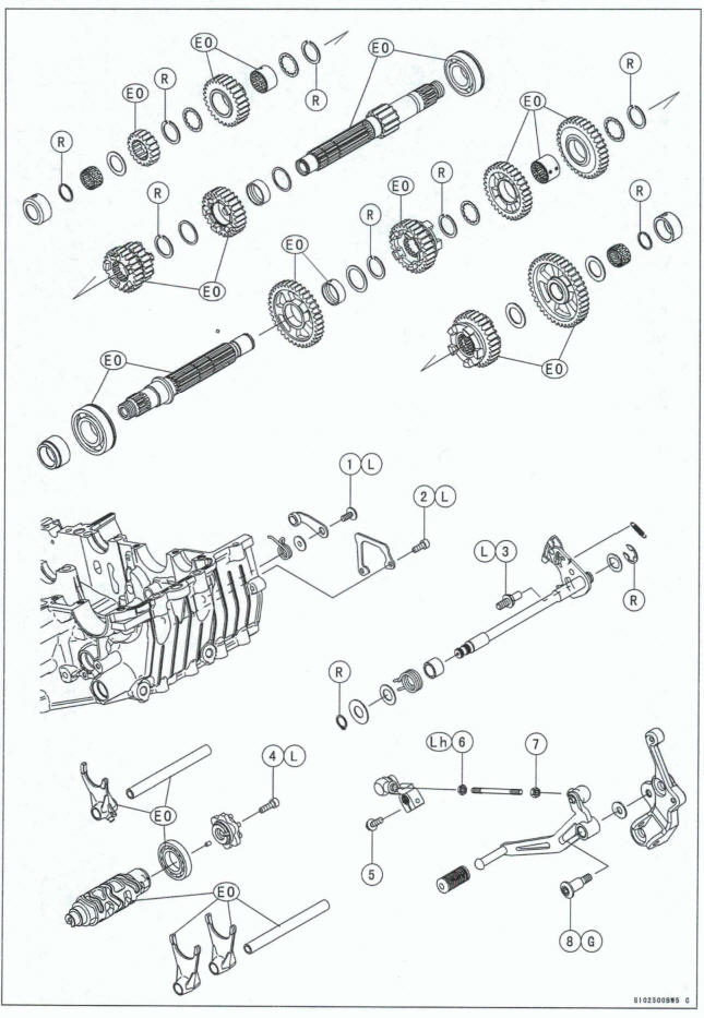
EO: Apply engine oil.
G: Apply grease.
L: Apply a non-permanent locking agent.
Lh: Left-hand Threads
R: Replacement Parts
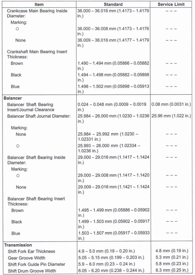
Specifications
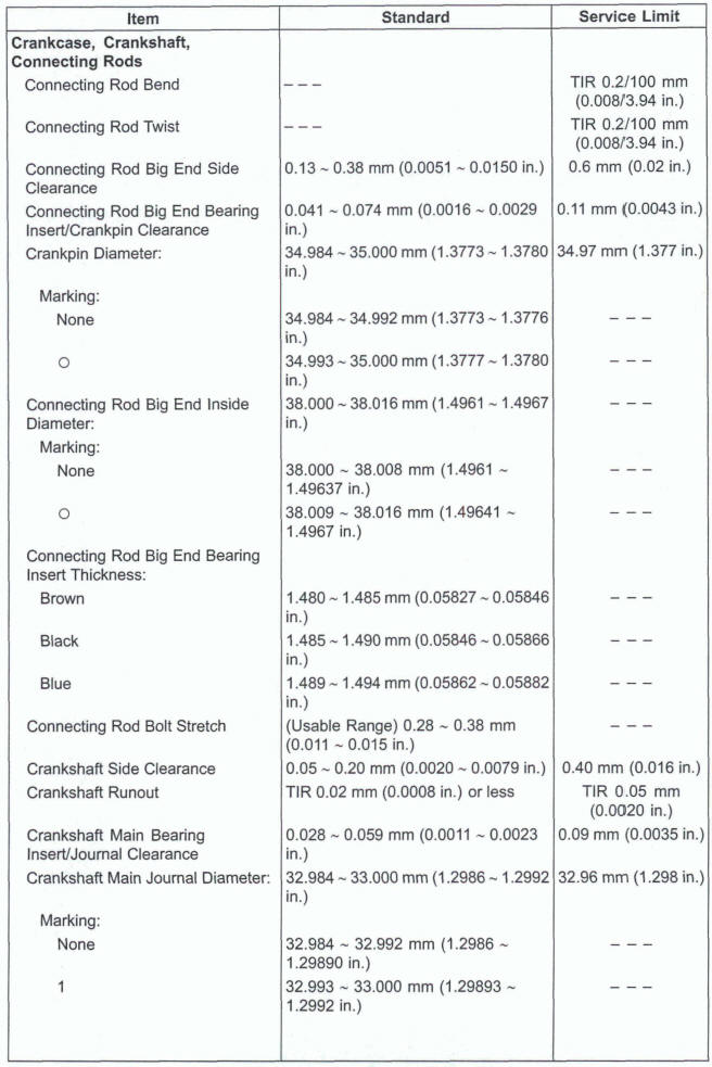
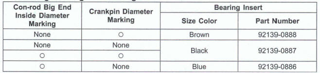
Connecting Rod Big End Bearing Insert Selection
Crankshaft Main Bearing Insert Selection
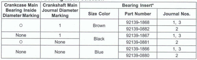
*: The bearing insert for Nos. 2 jornal have an oil groove.
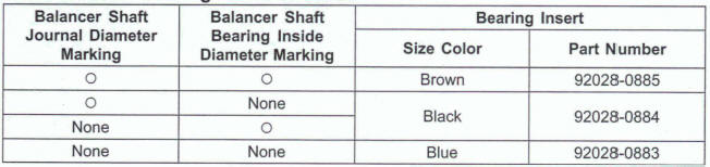
Balancer Shaft Bearing Insert Selection
Special Tools and Sealant
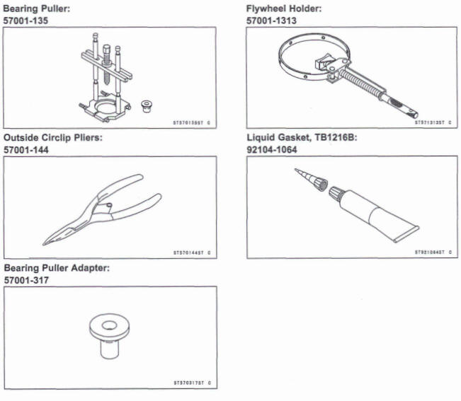
Crankcase
Crankcase Splitting
Remove the engine (see Engine Removal in the Engine Removal/Installation chapter).
Set the engine on a clean surface and hold the engine steady while parts are being removed.
Remove:
Cylinder (see Cylinder Removal in the ~n~ih6Efnod ~ chapter) Clutch (see Clutch Removal in the Clutch chapter) External Shift Mechanism (see External Shift Mechanism Removal) Oil Pump (see Oil Pump Removal in the Engine Lubrication System chapter) Starter Motor (see Starter Motor Removal in the Electrical System chapter) Alternator Rotor (see Alternator Rotor Removal in the Electrical System chapter) Water Pump (see Water Pump Removal in the Coding System chapter) Oil Filter (see Oil Filter Replacement in the Periodic Maintenance chapter) Oil Pressure Switch (see Oil Pressure Switch Removal in the Engine Lubrication System chapter) Camshaft Chain (see Camshaft Chain Removal in the Engine Top End chapter) Oil Pan (see Oil Pan Removal in the Engine Lubrication System chapter) Oil Screen (see Oil Pan Removal in the Engine Lubrication System chapter) Oil Pressure Relief Valve (see Oil Pressure Relief Valve Removal in the Engine Lubrication System chapter)
*If the crankshaft is to be removed, remove the pistons (see Piston Removal in the Engine Top End chapter).
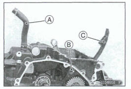
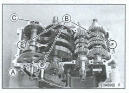
Remove: Breather Hose [A] Rear Camshaft Chain Guide Bolt [B] and Washer Rear Camshaft Chain Guide [C]
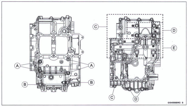
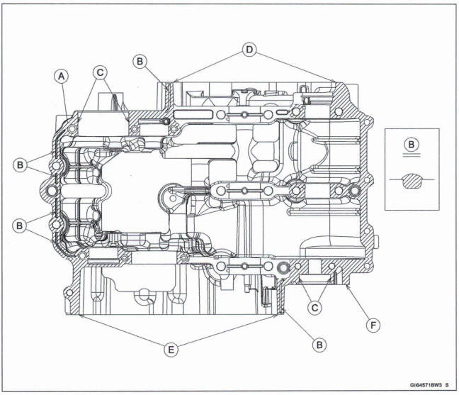
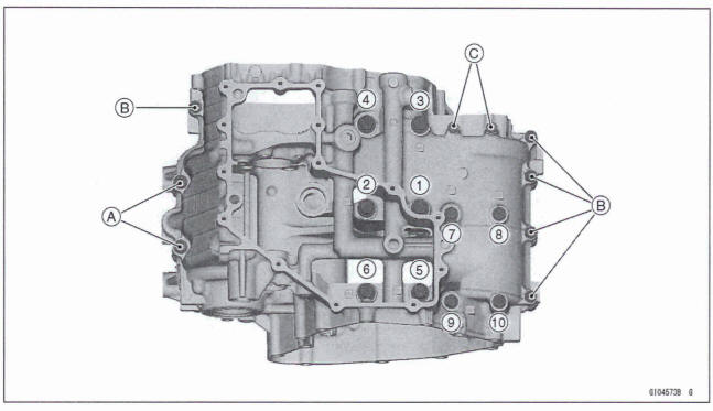
- Remove the upper crankcase bolts in order from the small
bolts.
M6 Bolts [A] M8 Bolts [B]
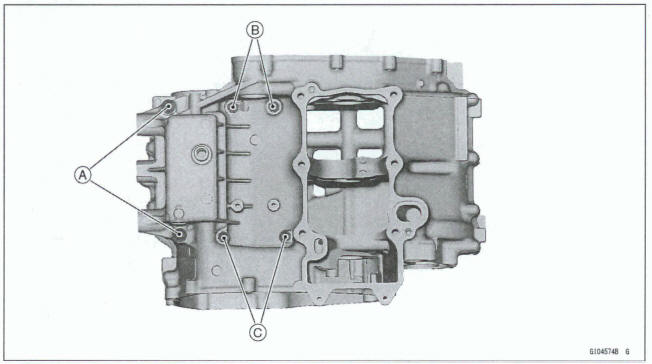
- Remove the lower crankcase bolts in order from the small
bolts.
M6 Bolts [C] M8 Bolts [D] M9 Bolts [E]
Tap lightly around the crankcase mating surface with a plastic mallet, and split the crankcase.
Take care not to damage the crankcase.
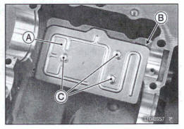
*If the breather plate [A] is to be removed, follow the next procedure.
- Remove: Transmission Shafts (see Transmission Shaft Removal) Oil Pipe (see Oil Pipe Removal in the Engine Lubrication System chapter
- Cut the gasket [B] around the plate.
- Remove: Breather Plate Bolts [C] Breather Plate
Crankcase Assembly
Notice
The upper and lower crankcase halves are machined at the factory in the assembled state, so the crankcase halves must be replaced as a set
- With a high flash-point solvent, dean off the mating surfaces of the crankcase halves and wipe dry.
Warning
Gasoline and low flashpoint solvents can be flammable and/or explosive and cause severe burns. Clean the crankcase In a well-ventilated area, and take care that there are no sparks or flame anywhere near the working area; this includes any appliance with a pilot light. Do not use gasoline or a low flash-point solvent to clean the crankcase.
- Using compressed air, blow out the oil passages in the crankcase halves.
Upper Crankcase Assembly
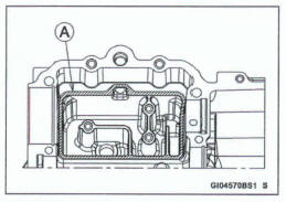
- Using a high flash-point solvent, dean off any oil or dirt on the mating surface of the breather plate.
- Apply liquid gasket to the mating surface [A] of the breather plate as shown.
Sealant - Liquid Gasket, TB1216B: 921 04-1 064
NOTE
- Make the application finish within 20 minutes when the liquid gasket (TB1216B) to the mating surface of the breather plate is applied.
- Moreover fit the plate and tighten the bolts just after application of the liquid gasket.
Apply a non-permanent locking agent to the breather plate bolts [A].
Tighten: Toque - Breather Plate Bob: 9.8 Nm (1.0 kgt*m, 87 in-lb)
After tightening the bolts, wipe the excess gasket from the oil pipe mounting holes [B].
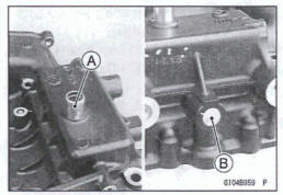
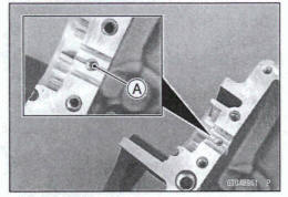
- Install the breather hose fitting [A] until it is bottomed.
- Install the plug [B] so that its surface is flush with the end of the hole.
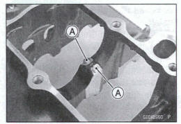
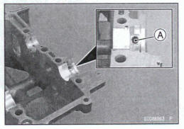
- Tighten: Toque -Oil Nozzles [A]: 3.0 Nm (0.31 kgf*m, 27 in-lb)
- Tighten: Toque -Oil Passage Nozzle(M5) [A]: 3.0 N*m (0.31 kgf*m, 27 in-lb)
Lower Crankcase Assembly
- Apply a non-permanent locking agent to the oil passage I plugs [A].
- Tighten: Toque - Oil Passage Plugs: 20 Nm (2.0 kgf-m, 15 ft-lb)
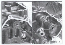
Tighten: Torque -Oil Passage Nozzle (M8) [A]: 5.0 Nm (0.M kgf*m 44 in-lb)
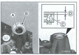
- Install the needle bearing [A] so that its surface is flush with the end of hole [B]
- Install the oil seal [C] as shown,.0.5~ 1.0 mm (0.02 ~0.04 in.) [D]
Crankcase Halves Assembly
- Install: Shift Drum (see Shift Drum and Fork Installation) - ' Shift Forks and Shift Rods (see Shift Drum and Fork Installation) Crankshaft (see Crankshaft Installation) Balancer Shaft (see Balancer Installation) Connecting Rods (see Connecting Rod Installation) Transmission Shafts and Gears (see Transmission Shaft Installation) Water pump Drive Shaft [A] Dowel Pins [B] cap [C]
- Before fitting the lower case on the upper case, check the following.
Check to see that the shift drum and transmission gears are in the neutral position.
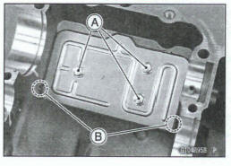
- Apply liquid gasket [A] to the mating surface of the lower crankcase half as shown.
Sealant - Liquid Gasket, TB1216B: 921061064
NOTE
- Especially, apply liquid gasket so that it shall be filled up on the grooves [B].
- Make the application finish within 20 minutes when the liquid gasket (TB1216B) to the mating surface of the lower crankcase half is applied.
- Moreover fit the case and tighten the bolts just after application of the liquid gasket
NOTICE
Do not apply liquid gasket around the crankshaft main bearing inserts, and oil passage holes.
- Fit the lower crankcase to the upper crankcase.
- Wipe off excess liquid gasket from the following portions.
Inside Diameter Surfaces [C]
Alternator Cover Mating Surface [D]
Clutch Cover Mating Surface [E]
Water Pump Housing Mating Surface [F]
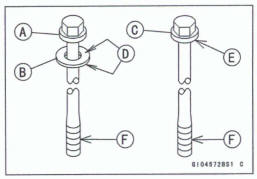
The M9 bolt [A] has a copper plated washer [B], replace them with new ones.
M6 and M8 Bolts [C]
Apply molybdenum disulfide oil solution to the following portions of M9 and M8 bolts.
Both Sides of Washer [D]
Seating Surface [E]
Threads [F]
- Firstly, tighten the M9 and M8 bolts temporarily following the specified sequence [1 ~10]
- Secondly, tighten the M9 and M8 bolts following the specified sequence [1 ~10]
Torque- Crankcase Bolts (M9): 10N*m (1.0 kgf*m, 89in*lb) Crankcase Bolts (M8, L= 70mm): 10 N*m (1.0 kgf*m, 89in*lb)
Thirdly, tighten the M9 bolts following the specified sequence [1~ 6]
Torque- Crankcase Bolts (M9): 30N*m (3.1 kgf*m, 22 in*lb)
Fourthly, tighten the M9 bolts 50º +- 2º
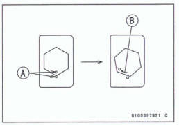
Mark [A] the crankcase and M9 bolts so that bolts can be turned 50º [B] properly
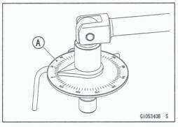
The bolts can be tightened by using a torque angle gauge [A]
- Fifthly, tighten the M8 bolts following the specified sequence [7~10].
Torque -Crankcase Bolts (M8, L = 70 mm): 27 N-m (2.8 kgf-m, 20 ft*lb)
- Sixthly, tighten the M8 bolts [A].
Torque - Crankcase Bolts (M8, L = 40 mm): 27.1 Nm (2.80 kgf-m, 20.3 ft*lb)
- Finally, tighten the Me bolts
Torque - Crankcase Bolts (M6): 11 N*m (1 .l kgf*m, 97 in*lb)
L = 30 mm (1.2 in.) [B]
L = 76 mm (3.0 in.) [C]
- Tighten:
Torque - Crankcase Bolts (M8,L = 80mm) [A] : 27.5 N*m (2.80 kgf*m, 20.3 ft*lb)
- Tighten:
Torque -Crankcase Bolts (M6): 11 N*m (1.1 kgf*m, 97 In-lb)
L = 72 mm (2.8 in.) [B]
L = 52 mm (2.0 in.) [C]
After tightening all crankcase bolts, check the following.
- Wipe up the liquid gasket that seeps out around the crankcase mating surface.
- Crankshaft and transmission shafts turn freely.
- While spinning the output shaft, gears shift smoothly from the 1st to 6th gear, and 6th to 1st.
- When the output shaft stays still, the gear can not be shifted to 2nd gear or other higher gear positions.
Install the removed parts (see appropriate chapters).
See also:
 Kawasaki Z400 - Service manual > Crankshaft and Connecting Rods
Crankshaft Removal Split the crankcase (see Crankcase Splitting). Remove: Crankshaft [A]
 Benelli Imperiale 400
 BMW F900XR
 Honda CB500X
 KTM 390 Adventure
 Triumph Street Triple S
 Yamaha MT-03
 Kawasaki Z400
 Triumph Street Triple S
 Yamaha MT-03