 Kawasaki Z400 - Service manual > Transmission
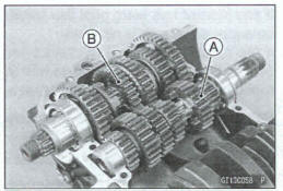
Transmission Shaft Removal
- Split the crankcase (see Crankcase Splitting).
- Remove the drive shaft [A] and output shaft [B].
Transmission Shaft Installation
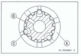
Check to see that the set pins [A] and set rings [B] me in place.
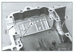
- Apply engine oil to the bearings and transmissions gears.
- The bearing set pins and rings must match properly with the holes or grooves in the bearing outer races. When they are properly matched, there is no clearance [A] between the crankcase and the bearing outer races.
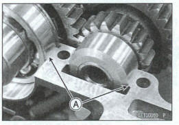
- Assemble the crankcase (see Crankcase Assembly).
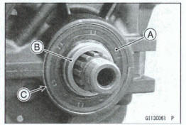
- Replace the oil seal [A] with a new one.
- Apply grease to the oil seal lips.
- Press in the oil seal onto collar [B] so that the surface of the oil seal is flush with the surface [C] of the crankcase.
Transmission Shaft Disassembly
- Remove the transmission shafts (see Transmission Shaft Removal).
- Remove the circlips, disassemble the transmission shah.
Special Tool - Outside Circlip Pliers: 57001444
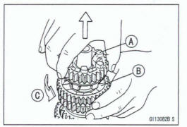
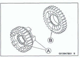
The 5th gear [A] on the output shaft has three steel balls assembled into it for the positive neutral finder mechanism.
Remove the 5th gear.
- Set the output shaft in a vertical position holding the 3rd gear [B].
- Spin the 5th gear quickly [C] and pull it off upward.
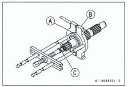
- Remove the ball bearing [A] from each shafts.
Special Tools - Bearing Puller [B]: 57001 -135 Bearing Puller Adapter [C]: 57001-317
- Discard the bearing.
Transmission Shaft Assembly
Apply engine oil to the bushings, ball bearings and shafts.
Install the ball bearings on the shafts with the groove toward the clutch side.
Install the gear bushings [A] on the shaft with their holes [B] aligned.
Replace any circlips removed with new ones.
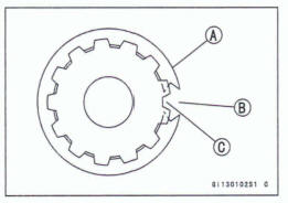
Install the circlips [A] so that the opening [B] is aligned with a spline groove [C]. ,
- The drive shaft gears can be recognized by size: the gear with the smallest diameter is 1 st gear, and the largest one is 6th gear. Be sure that all parts are put back in the correct sequence and all circlips and washers are properly in place.
- Install the 6th gear bushing onto the drive shaft with their oil holes aligned.
- The output shaft gears can be recognized by size: the gear with the largest diameter is 1st gear, and the smallest one is 6th gear. Be sum that all parts are put back in the correct sequence and all circlips and washers are properly in place.
- Install the 6th gear onto the output shaft with their oil holes aligned.
- Install the 2nd and 3rd/4th gear bushings onto the output shaft with their oil holes aligned.
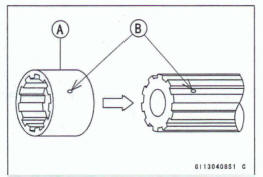
Fit the steel balls into the 5th gear holes in the output shaft, aligning oil hole as shown.
5th Gear [A] Output Shaft [B] Steel Balls [C]
Notice
Do not apply grease to the balls to hold them in place. This will cause the positive neutral finder mechanism to malfunction.
After assembling the 5th gear with steel balls in place on the output shaft, check the ball-locking effect that the 5th gear does not come out of the output shaft when moving it up and down by hand.
- Check that each gear spins or slides freely the transmission shafts without biding after assembly.
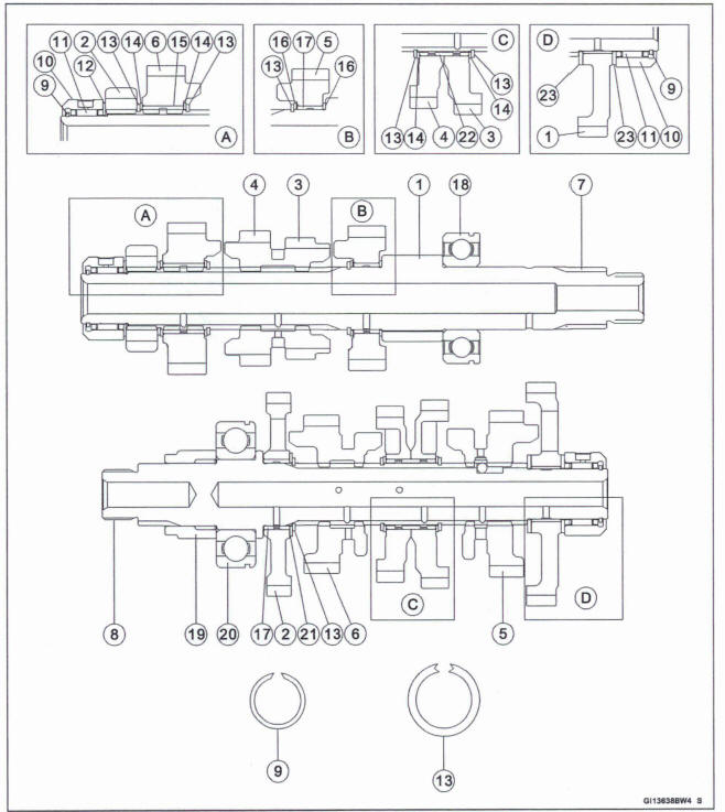
- 1 st Gear
- 2nd Gear
- 3rd Gear
- 4th Gear
- 581 Gear
- 6th (Top) Gear
- Drive Shaft
- Output Shaft
- Circlip
- Bearing Outer Race
- Needle Bearing
- Washer, 430 x 20.5 mm (1.2 x 0.8 in.)
- Circlip
- Toothed Washer
- Toothed Bushing, L = 16.6 mm (0.65 in.)
- Washer,
 30 x 25.3 mm (1.2 x
1.0 in.)
30 x 25.3 mm (1.2 x
1.0 in.) - Bushing,
 28 mm (1.1 in.)
 - Ball Bearing,
 52 mm (2.0
in.)
52 mm (2.0
in.) - Collar
- Ball Bearing,
 58 mm (2.3
in.)
58 mm (2.3
in.) - Washer,
 33 x 25.3 mm (1.3 x
1.0 in.)
33 x 25.3 mm (1.3 x
1.0 in.) - Toothed Bushing, L = 20.0 mm (0.79 in.)
- Washer,
 31 x 20.5 mm (1.2 x
0.8 in.)
31 x 20.5 mm (1.2 x
0.8 in.)
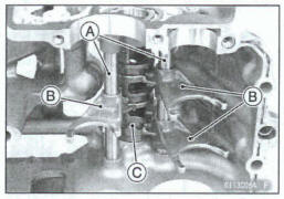
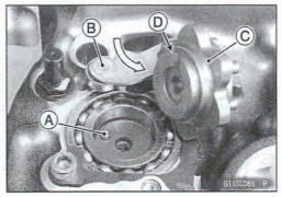
Shift Drum and Fork Removal
- Remove:
Transmission Shafts (see Transmission Shaft Removal)
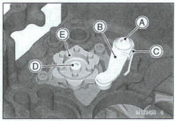
Gear Positioning Lever Bolt [A]
Gear Positioning Lever [B]
Spacer
Spring [C]
Shift Drum Cam Bolt [D]
Shift Drum Cam [E]
Pin
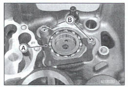
- Remove:
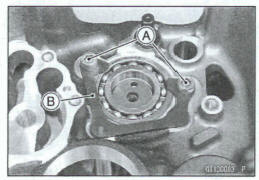
Shift Drum Bearing Holder Bolts [A]
Shift Drum Bearing Holder [B]
- Remove:
Shift Rods [A]
Shift Forks [B]
Shift Drum [C] and Bearing
Shift Drum and Fork Installation
Apply molybdenum disulfide oil solution to the following parts.
Shift Drum
Shift Forks
Shift Rods
- Install: Shift Drum [A] Shift Drum Bearing [B]
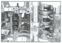
- Install: Shift Rods [A] Shift Fork (For Drive Shaft) [B] Shift Forks (For Output Shaft) [C]
Face the stoppers [D] on the shift forks inward.
FR the shift fork pins to the shift drum grooves as shown.
- In stall: Shift Drum Bearing Holder [A]
- Apply a non-permanent locking agent to the shift drum bearing holder bolts [B].
- Tighten the bolts temporarily.
- Tighten:
Torque -Shift Drum Bearing Holder Bob: 9.8 N-m (1.0 kgf-m, 87 in-lb)
- In stall: Spring [A] Spacer [B] Gear Positioning Lever [C]
- Apply a non-permanent locking agent to the gear positioning lever bolt [D].
- Tighten: Torque -Gear Positioning Lever Bolt: 9.8 N-m (1.0 kgf*m, 87 In-lb)
- Check the gear positioning lever and spring for smooth operation.
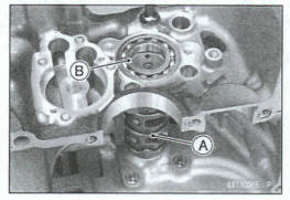
- In stall: Pin [A]
- While pushing the gear positioning lever [B], install the shift drum cam [C].
Align the groove [D] with the pin.
- Apply a non-permanent locking agent to the shift drum cam belt.
- Tighten: Toque -Shift Drum Cam Bolt: 12 N-m (1.2 kgf-m, 106 in*lb)
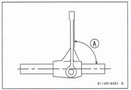
Shift Fork Bending Inspection
- Visually inspect the shift forks, and replace any fork that is bent. A bent fork could cause difficulty in shifting, or allow the transmission to jump out of gear when under power.90º[A]
Shift Fork/Gear Groove Wear Inspection
- Measure the thickness of the shift fork ears (A], and measure the width of the gear grooves [B].
*If the thickness of a shift fork ear is less than the service limit, the shift fork must be replaced.
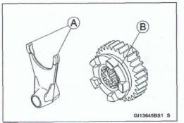
Shift Fork Ear Thickness
Standard 4.9 - 5.0 mm (0.19 - 0.20 In.)
Service Limit: 4.8 mm (0.19 In.)
*If the gear groove is worn over the service limit, the gear must be replaced.
Gear Groove Width
Standard: 5.05 - 5.15 mm (0.199 - 0.203 in.)
Service Limit: 5.3 mm (0.21 in.)
Shift Fork Guide Pin/Drum Groove Wear Inspection
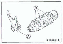
- Measure the diameter of each shift fork guide pins [A], and measure the width of each shift drum grooves [B].
*If the guide pin on any shift fork is less than the service limit, the fork must be replaced
Shift Fork Guide Pin Diameter
Standard: 5.9 - 6.0 mm (0.23 - 0.24 in.)
Service Limit: 5.8 mm (0.23 In.)
*If any shift drum groove is worn over the service limit, the drum must be replaced
Shift Drum Groove Width
Standard: 6.05 - 6.20 mm (0.238 - 0.244 in.)
Service Limit: 6.3 mm (0.25 in.)
Gear Dog and Gear Dog Hole Damage Inspection
- Visually inspect the gear dogs [A] and gear dog holes [B].
*Replace any damaged gears or gears with excessively worn a or dog holes.
See also:
 Kawasaki Z400 - Service manual > Balancer
Balancer Removal Split the crankcase (see Crankcase Splitting). Remove the balancer shaft [A] with the balancer gear.
Kawasaki Z400 - Service manual > External Shift Mechanism
Shift Pedal Removal Remove the shift lever damp bolt [A], and disconnect the shift lever [B] from the shift shaft. Remove: Shift Pedal Bolt [C] Shift Pedal [D] Washer
 Benelli Imperiale 400
 BMW F900XR
 Honda CB500X
 KTM 390 Adventure
 Triumph Street Triple S
 Yamaha MT-03
 Kawasaki Z400
 Triumph Street Triple S
 Yamaha MT-03