 Kawasaki Z400 - Service manual > Crankshaft and Connecting Rods
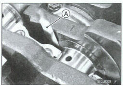
Crankshaft Removal
- Split the crankcase (see Crankcase Splitting).
- Remove: Crankshaft [A]
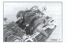
Crankshaft Installation
NOTE
If the crankshaft is replaced with a new one, refer to the Connecting Rod Big End Bearing insert Selection in the Specifications.
NOTICE
If the crankshaft, bearing inserts, or crankcase halves are replaced with new ones, select the bearing inserts and check clearance with a plastigage (press gauge) before, assembling engine to be run, the comet bearing Inserts are installed.
- Apply molybdenum disulfide oil solution to the crankshaft main bearing inserts.
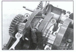
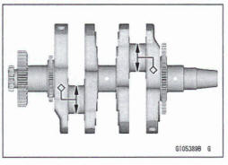
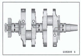
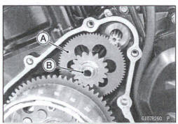
- Install the crankshaft [A].
Align the timing marks [B].
Balancer [C]
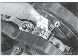
Connecting Rod Removal
- Split the crankcase (see Crankcase Splitting).
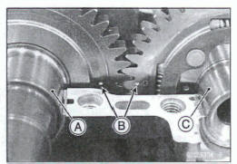
- Remove: Connecting Rod Big End Nuts [A]
NOTE
Mark and record the locations of the connecting rods and their big end caps [B] so that they can be reassembled in their original positions.
- Remove the connecting rods from the crankshaft
Notice
Discard the connecting rod bolts. To prevent damage to the crankpin surfaces, do not allow the connecting rod bolts to bump against the crankpins.
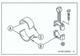
Connecting Rod Installation
NOTICE
To minimize vibration, the connecting rods should have the same weight mark.
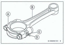
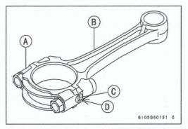
Big End Cap [A]
Connecting Rod [B]
Weight Mark, Alphabet [C]
Diameter Mark (Around Weight Mark) [D] : '0' or no mark
NOTICE
If the connecting rods, big end bearing Inserts, or crankshaft are replaced with new ones, select the bearing insert and check clearance with a plastigage (press gauge) before assembling engine to be sure the correct bearing inserts are installed.
NOTICE
The connecting rod bolts are designed to stretch when tightened. Never reuse them.
- Replace the connecting rod big end bolts and nuts with new ones.
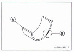
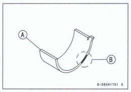
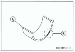
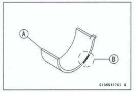
- Apply molybdenum disulfide oil solution to the inner surfaces of upper and lower bearing inserts [A].
- Do not apply any grease or oil to the cap inside and cap insert outside [B].
- Install the inserts so that their nails [C] are on the same side and fit them into the recess of the connecting rod and cap.
NOTICE
Wrong application of oil and grease could cause bearing damage.
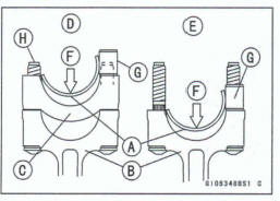
When installing the inserts [A], be careful not to damage the insert surface with the edge of the connecting rod [B] or the cap [C]. One way to install inserts is as follows.
Installation p] to Cap
Installation [E] to Connecting Rod
Push [F]
Spare Dowel Pin [G]
Connecting Rod Bob [H]
- Install the cap on the connecting rod, aligning the weight and diameter marks.
- Remove debris and clean the surface of inserts.
- Install each connecting rod on its original crankpin.
The connecting rod big end is bolted using the "plastic region fastening method".
This method precisely achieves the needed clamping force without exceeding it unnecessarily, allowing the use of thinner, lighter bolts further decreasing connecting rod weight.
There are two types of the plastic region fastening. One is a bolt length measurement method and other is a rotation angle method. Observe one of the following two, but the bolt length measurement method is preferable because this is a more reliable way to tighten the big end nuts.
NOTICE
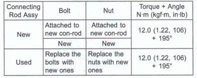
The connecting rod bolts are designed to stretch when tightened. Never reuse the connecting rod bolts. See the table below for correct bolt and nut usage.
NOTICE
Be careful not to overtighten the nuts.
The bolts must be positioned on the seating surface correctly to prevent the bolt heads from hitting the crankcase.
1) Bolt Length Measurement Method
- Be sure to dean the bolts, nuts, and connecting rods thoroughly with a high flash-point solvent, because the new connecting rods, bolts, and nuts are treated with an anti-rust solution.
WARNING
Gasoline and low flash-point solvents can be flammable and/or explosive and cause severe burns. Clean the bob, nuts, and connecting rods in a well-ventilated am, and take care that there are no sparks or flame anywhere near the working area; this includes any appliance with a pilot light.
Do not use gasoline or a low flash-point solvent to clean them.
NOTICE
Immediately dry the bolts and nuts with compressed air after cleaning. Clean and dry the bolts and nuts completely.
- Install new bolts and nuts in reused connecting rod.
*If the connecting rod assy was replaced, use the new bolts and nuts attached to the new connecting rod assy.
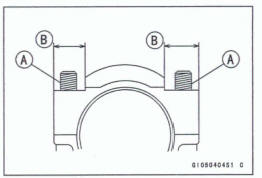
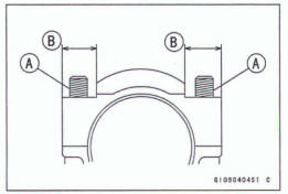
- Apply a small amount of molybdenum disulfide oil solution to the following portions.
Threads [A] of Nuts and Bolts
Seating Surfaces [B] of Nuts and Connecting Rods
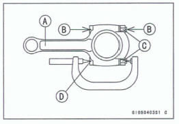
- Dent both bolt head and bolt tip with a punch as shown.
- Before tightening, use a point micrometer to measure the length of new connecting rod bolts and record the values to find the bolt stretch.
Connecting Rod [A]
Dent here with a punch [B].
Nuts [C]
Fit micrometer pins into dents [D].
- Tighten the big end nuts until the bolt elongation reaches
the length specified as follows.

Connecting Rod Bolt Stretch Usable Range: 0.28 ~ 0.38 mm (0.011 ~ 0.015 in.)
- Check the length of the connecting rod bolts.
*If the stretch is more than the usable range, the bolt has stretched too much. An overelongated bolt may break in use.
(2) Rotation Angle Method
*If you do not have a point micrometer, you may tighten the nuts using the "Rotation Angle Method".
- Be sure to clean the bolts, nuts and connecting rods thoroughly with a high flash-point solvent, because the new connecting rods, bolts and nuts are treated with an anti -rust solution.
WARNING
Gasoline and low flash-point solvents can be flammable and/or explosive and cause severe bums. Clean the bolts, nuts, and connecting rods in a well-ventilated area, and take care that there are no sparks or flame anywhere near the working area; this includes any appliance with a pilot light.
Do not use gasoline or a low flash-point solvent to clean them.
Notice
Immediately dry the bolts and nuts with compressed air after cleaning.
Clean and dry the bolts and nuts completely.
- Install new bolts and nuts in reused connecting rod.
*If the connecting rod assy was replaced, use the new bolts and nuts attached to the new connecting rod assy.
- Apply a small amount of molybdenum disulfide oil solution to the following portions
Threads [A] of Nuts and Bolts
Seating Surfaces [B] of Nuts and Connecting Rods
*If the connecting rod assy was replaced, use the new bolts and nuts attached to the new connecting rod assy.
- Apply a small amount of molybdenum disulfide oil solution to the following portions
Threads [A] of Nuts and Bolts
Seating Surfaces [B] of Nuts and Connecting Rods
- First, tighten the nuts with 12.0 Nm (1.22 kgf*m, 106 in-lb) of toque.
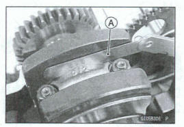
- Next, tighten the nuts 195º.
Mark [A] the connecting rod big end caps and nuts so that nuts can be turned 195º [B] properly.
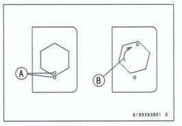
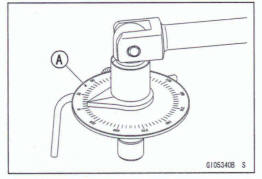
The nuts can be tightened by using a torque angle gauge [A].
Crankshaft/ Connecting Rod Cleaning
- After removing the connecting rods from the crankshaft, dean them with a high flash-point solvent.
- Blow the crankshaft oil passages with compressed air to remove any foreign particles or residue that may have accumulated in the passages.
Connecting Rod Bend Inspection
- Remove the connecting rod big end bearing inserts, and reinstall the connecting rod big end cap.
- Select an arbor [A] of the same diameter as the connecting rod big end, and insert the arbor through the connecting rod big end.
- Select an arbor of the same diameter as the piston pin and at least 100 mm (3.94 in.) long, and insert the arbor [B] through the connecting rod small end.
- On a surface plate, set the big-end arbor on V block [C].
- With the connecting rod held vertically, use a height gauge to measure the difference in the height of the arbor above the surface plate over a 100 mm (3.94 in.) length to determine the amount of connecting rod bend.
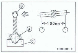
*If the connecting rod bend exceeds the service limit, the connecting rod must be replaced.
Connecting Rod Bend Service Limit: TIR O.2/100 mm (0.00813.94 in.)
Connecting Rod Twist Inspection
- With the big-end arbor [A] still on V block [B], hold the connecting rod horizontally and measure the amount that the arbor [C] varies from being paralleled with the surface plate over a 100 mm (3.94 in.) length of the arbor to determine the amount of connecting rod twist
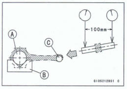
*If the connecting rod twist exceeds the service limit, the connecting rod must be replaced
Connecting Rod Twist Service Limit: TIR 0.2/100 mm (0.00813.94 in.)
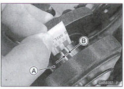
Connecting Rod Big End Side Clearance Inspection
Measure the connecting rod big end side clearance.
Insert a thickness gauge [A] between the big end and either crank web to determine clearance
Connecting Rod Big End Side Clearance
Standard: 0.13 - 0.38 mm (0.0051 - 0.0150 in.) Service Limit: 0.6 mm (0.02 in.)
*If the clearance exceeds the service limit, replace the connecting rod with new one and then check the clearance again. If the clearance is too large after connecting rod replacement, the crankshaft also must be replaced.
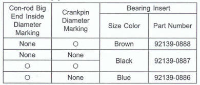
Connecting Rod Big End Bearing Insert/Crankpin Wear inspection
- Measure the bearing insert/crankpin [A] clearance with plastigage [B].
- Tighten the bi end nuts to the specified torque (see Connecting Rod Installation).
NOTE
Do not move the connecting rod and crankshaft during clearance measurement.
Connecting Rod Big End Baring Insert/Crankpin Clearance Standard: 0.041 ~ 0.074 mm (0 .0016 ~ 0.0029 in.) Service Limit: 0.11 mm (0.0043 in.)
*If the clearance is within the standard, no bearing replacement is required.
*If the clearance is between 0.059 mm (0.0023 in.) and the service limit 0.10 mm (0.0039 in.), replace the bearing inserts [A] with inserts painted blue [B]. Check the insert/crankpin clearance with the plastigage. The clearance may exceed the standard slightly, but it must not be less than the minimum in order to avoid bearing seizure.
*If the clearance exceeds the service limit, measure the diameter of the crankpins.
Crankpin Diameter Standard: 34.984 - M.000 mm (1.3773 - 1.3786 In.) Service Limit: 34.97 mm (1.377 in.)
*If any crankpin has warn pat the service limit, replace the crankshaft with a new one.
*If the measured crankpin diameters are not less than the service limit, but do not coincide with the original diameter markings on the crankshaft, make new marks on it.
Crankpin Diameter Marks
None: 34.984 - 34992 mm (1.3773 ~ 1.3776 in.)
 : 34.99% - 35.000 mm (1 .3777~
1.3780 in.)
: 34.99% - 35.000 mm (1 .3777~
1.3780 in.)
 : Crankpin Diameter Marks, "0"or
no mark.
: Crankpin Diameter Marks, "0"or
no mark.
- Measure the connecting rod big end inside diameter, and mark each connecting rod big end in accordance with the inside diameter.
- Tighten the connecting rod big end nuts to the specified torque (see Connecting Rod Installation).
NOTE
The mark already on the big end should almost coincide with the measurement.
Connecting Rod Big End Inside Diameter Marks
None: 38.000 ~ 38.008 mm (1.4961~ 1.49637 In.)
 : 38.009
~ 38.016 mm (1.49641
~ 1.4967 In.)
: 38.009
~ 38.016 mm (1.49641
~ 1.4967 In.)
Big End Cap [A]
Connecting Rod [B]
Weight Mark, Alphabet [C]
Diameter Mark (Around Weight Mark) [D] : *O* or no mark
- Select the proper bearing insert [A] in accordance with the
combination of the connecting rod and crankshaft coding.
Size Color [B]
- Install the new inserts in the connecting rod and check insert/crankpin clearance with the plastigage
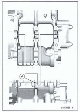
Crankshaft Side Clearance Inspection
- Insert a thickness gauge [A] between the crankcase main bearing and the crank web at the No. 2 journal to determine clearance.
*If the clearance exceeds the service limit, replace the crankcase halves as a set
NOTE
The upper and lower crankcase halves are machined at the factory in the assembled state, so the crankcase halves must be replaced as a set.
Crankshaft Side Clearance
Standard: 0.05 - 0.20 mm (0.0020 - 0.0079 In.)
Service Limit: 0.40 mm (0.016 In.)
Crankshaft Runout Inspection
- Measure the crankshaft runout.
*If the measurement exceeds the service limit, replace the crankshaft.
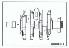
Crankshaft Runout
Standard: TIR 0.02 mm (0.0008 in.) or less
Service Limit: TIR 0.05 mm (0.0020 in.)
Crankshaft Main Bearing Insert/Jouma1 Wear Inspection
- Using a plastigaqe (press gauge) [A], measure the bearing insert/journal [B] clearance.
NOTE
- Tighten the crankcase bolts to the specified toque (see Crankcase Assembly).
- Do not turn the crankshaft during clearance measurement.
- Journal clearance than an 0.025 mm (0.00098 in.) can not be measured by plastigage, however, using genuine parts maintains the minimum standard clearance.
Crankshaft Main Bearing insert/Journal Clearance
Standard: 0.028 ~ 0.059 mm (0.0011~ 0.0023 in.)
Service Limit: 0.09 mm (0.0035 in.)
*If the clearance is within the standard, no bearing replacement is required.
*If the clearance is between 0.059 mm (0.0023 in.) and the service limit 0.09 mm (0.0035 in.), replace the bearing inserts [A] with inserts painted yellow [B]. Check insert/journal clearance with the plastigage. The clearance may exceed the standard slightly, but it must not be less than the minimum in order to avoid bearing seizure.
*If the clearance exceeds the service limit, measure the diameter of the crankshaft main journal.
Crankshaft Main Journal Diameter
Standard: 32.984~33.000 mm (1.2986~ 1.2992 in.)
Service Limit: 32.96 mm (1 298 in.)
*If any journal has worn past the service limit, replace the crankshaft with a new one.
*If the measured journal diameters are not less than the service limit, but do not coincide with the original diameter markings on the crankshaft, make new marks on it.
Crankshaft Main Journal Diameter Marks
None: 32.984 ~ 32.992 mm (1.2986 ~ 1.29890 in.)
1 : 32.993~ 33.000 mm (1.29893 ~ 1.2992 in.)
 : Crankshaft Main Journal
Diameter Marks, "1" or no
mark.
: Crankshaft Main Journal
Diameter Marks, "1" or no
mark.
- Measure the main bearing inside diameter, and mark the upper crankcase half in accordance with the inside diameter.
[A]: Crankcase Main Bearing Inside Diameter Marks, "O" or no mark.
NOTE
- Tighten the crankcase bolts to the specified toque (see Crankcase Assembly).
- The mark already on the upper crankcase half should almost coincide with the measurement.
Crankcase Main Bearing Inside Diameter Marks
0 : 36.000 ~ 36.008 mm (1.4173 ~1.4176 In.)
None: 36.009~ 36.016 mm (1.4177~ 1.4179 in.)
- Select the proper bearing insert [A] in accordance with the combination of the crankcase and crankshaft coding.
Size Color [B]
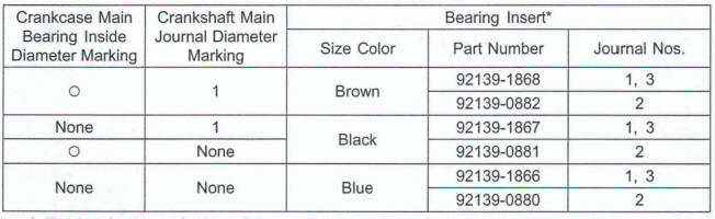
*: The bearing insert for Nos. 2 journal have an oil groove.
- Install the new inserts in the crankcase halves and check insert/journal clearance with the plastigage
Starter Motor Clutch Removal/Installation
- Refer to the Alternator Rotor Removal/Installation in the Electrical System chapter.
Starter Motor Clutch Inspection
- Remove: Alternator Cover (see Alternator Cover Removal in the Electrical System chapter) Starter Idle Gear [A] and Shaft [B]
- Disassemble the starter motor clutch, and visually inspect the clutch parts.
*If there is any worn or damaged part, replace it.
Note
Examine the started motor clutch gear as well. Replace it if it worn or damaged
Starter Motor Clutch Disassembly
- Remove: Alternator Rotor (see Alternator Rotor Removal in the Electrical System chapter) Starter Motor Clutch Bolts [A] Starter Motor Clutch
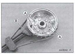
Special Tool - Flywheel Holder [B] : 51001-1313
Starter Motor Clutch Assembly
- Apply a non-permanent locking agent to the threads of the starter motor clutch bolts and tighten them.
Special Tool - Flywheel Holder: 51001-1313
Torque - Starter Motor Clutch Bolts: 12 N*m (1.2 kgf-m, 106 In-lb)
See also:
 Kawasaki Z400 - Service manual > Crankshaft/Transmission
Exploded View
Kawasaki Z400 - Service manual > Balancer
Balancer Removal Split the crankcase (see Crankcase Splitting). Remove the balancer shaft [A] with the balancer gear.
 Benelli Imperiale 400
 BMW F900XR
 Honda CB500X
 KTM 390 Adventure
 Triumph Street Triple S
 Yamaha MT-03
 Kawasaki Z400
 Triumph Street Triple S
 Yamaha MT-03