 Yamaha MT-03 - Service manual > Crankcase
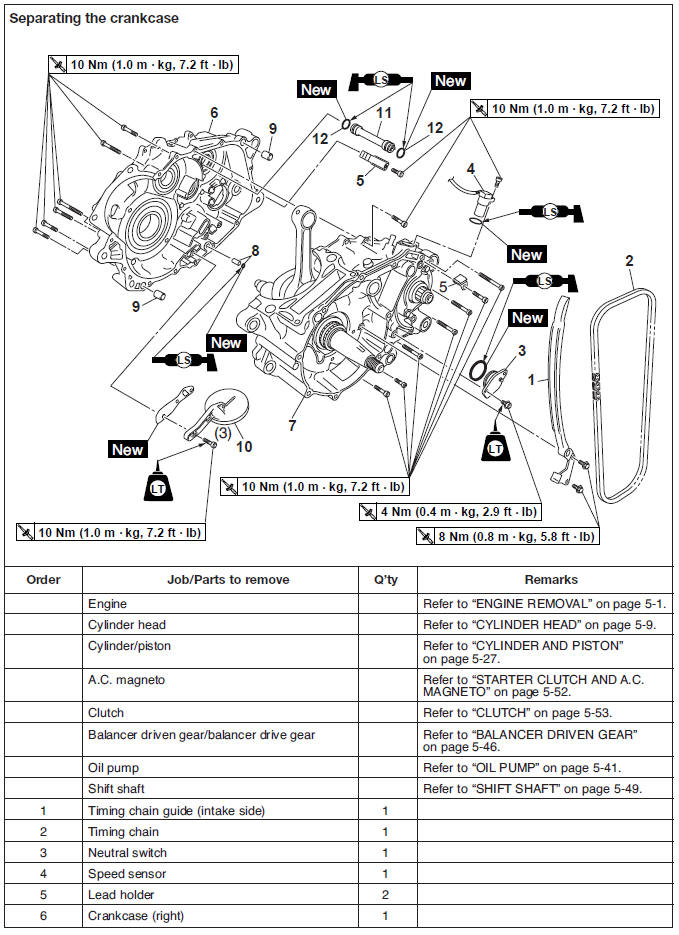
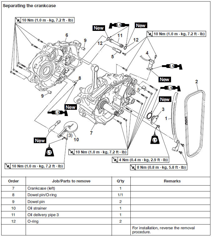
Separating the crankcase
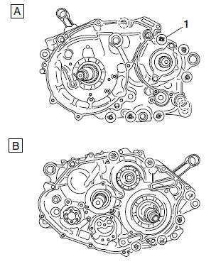
1. Separate:
- Right crankcase "1"
- Left crankcase "2"
a. Remove the crankcase bolts.
NOTE:
- Loosen each bolt 1/4 of a turn at a time and after all the bolts are loosened, remove them.
- Loosen the bolts in stages, using a crisscross pattern.
b. Remove the right crankcase.
NOTE:
Insert a screwdriver or pry bar into the pry points in the crankcase and then carefully pry apart the crankcase halves.
CAUTION:
Use a soft hammer to tap on one side of the crankcase. Tap only on reinforced portions of the crankcase. Do not tap on the crankcase mating surfaces. Work slowly and carefully. Make sure that the crankcase halves separate evenly.
c. Remove the dowel pins and O-ring.
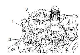
Checking the oil strainer and oil delivery pipe 3
1. Check:
- Oil strainer
Damage → Replace.
Contaminants → Clean with engine oil.
2. Check:
- Oil delivery pipe 3.
Cracks/damage → Replace.
- Oil delivery pipe holes "1".
Clogged → Blow out with compressed air.
Checking the timing chain and timing chain guides
1. Check:
- Timing chain.
Damage/stiffness → Replace the timing chain and camshaft sprocket as a set.
2. Check:
- Timing chain guide (intake side) Damage/wear → Replace.
Checking the bearings and oil seals
1. Check:
- Bearings
Clean and lubricate the bearings, and then rotate the inner race with your finger.
Rough movement → Replace.
2. Check:
- Oil seals
Damage/wear → Replace.
Checking the crankcase
1. Thoroughly wash the crankcase halves in a mild solvent.
2. Thoroughly clean all the gasket surfaces and crankcase mating surfaces.
3. Check:
- Crankcase.
Cracks/damage → Replace.
- Oil delivery passages.
Obstruction → Blow out with compressed air.
Assembling the crankcase
1. Lubricate:
- Bearings
- Oil seals
 Recommended lubricant
Bearing
Engine oil
Oil seal
Lithium-soap-based grease
Recommended lubricant
Bearing
Engine oil
Oil seal
Lithium-soap-based grease
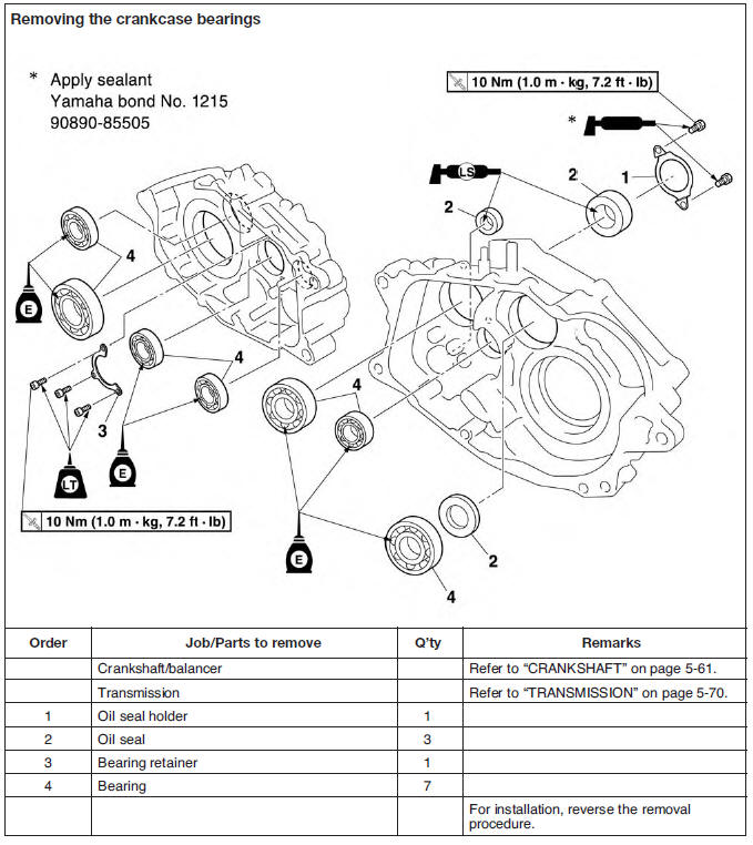
2. Install:
- Bearings

- Bearing retainer "1" (to the right crankcase)
- Bearing retainer bolts
 Bearing retainer bolts
10 Nm (1.0 m*kg, 7.2 ft*lb)
Bearing retainer bolts
10 Nm (1.0 m*kg, 7.2 ft*lb)
NOTE:
Install the bearing retainer with the "OUT" mark "a" facing up.
3. Thoroughly clean all the gasket mating surfaces and crankcase mating surfaces.
4. Apply:
- Yamaha bond No. 1215 "1" (to the mating surfaces of both crankcase halves)
 Yamaha bond No. 1215
90890-85505
Yamaha bond No. 1215
90890-85505
NOTE:
Do not allow any sealant to come into contact with the oil gallery.
5. Install:
- Dowel pins
- O-rings

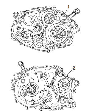
6. Fit the right crankcase onto the left crankcase.
Tap lightly on the case with a soft hammer.
CAUTION:
Before installing and torquing the crankcase bolts, be sure to check whether the transmission is functioning properly by manually rotating the shift drum in both directions.
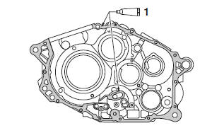
7. Install:
- Lead holder "1"
- Crankcase bolts
 Left crankcase
 Right crankcase
8. Tighten:
- Crankcase bolts (follow the proper tightening sequence)
 Crankcase bolts
10 Nm (1.0 m*kg, 7.2 ft*lb)
Crankcase bolts
10 Nm (1.0 m*kg, 7.2 ft*lb)
NOTE:
Tighten the bolts in stages, using a crisscross pattern.
9. Apply:
- 4-stroke engine oil (to the crankshaft pin, bearing, and oil delivery hole)
10.Check:
- Crankshaft and transmission operation Unsmooth operation → Repair.
11.Install:
- Speed sensor
 Speed sensor bolts
10 Nm (1.0 m*kg, 7.2 ft*lb)
Speed sensor bolts
10 Nm (1.0 m*kg, 7.2 ft*lb)
- Neutral switch
- Neutral switch screw
 Neutral switch screw
4 Nm (0.4 m*kg, 2.9 ft*lb)
LOCTITE
Neutral switch screw
4 Nm (0.4 m*kg, 2.9 ft*lb)
LOCTITE
Crankshaft
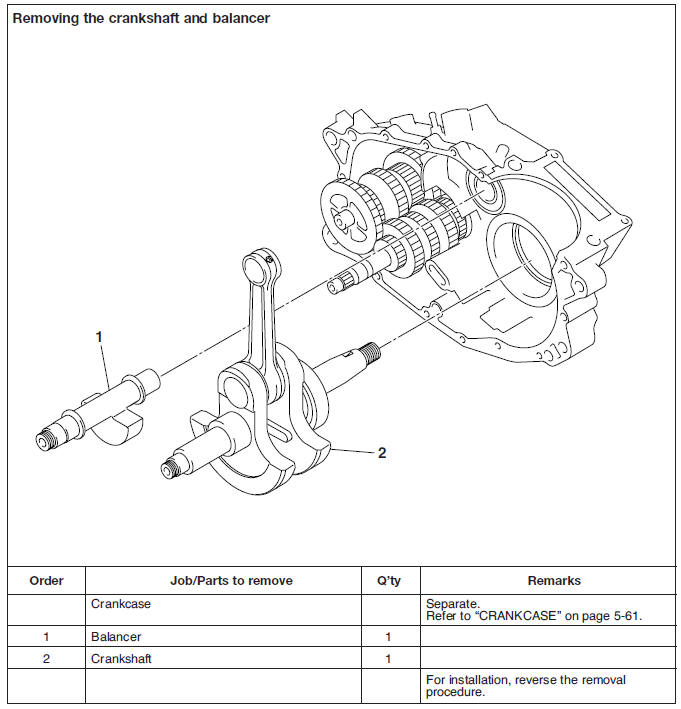
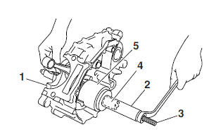
Removing the crankshaft assembly
1. Remove:
- Crankshaft "1"
NOTE:
- Remove the crankshaft with the crankcase separating tool "2".
- Make sure the crankcase separating tool is centered over the crankshaft.
 Crankcase separating tool
90890-01135
Crankcase separating tool
90890-01135
Checking the crankshaft
1. Measure:
- Big end side clearance "d" Out of specification → Replace the big end bearing, crankshaft pin, or connecting rod.
 Big end side clearance
0.350-0.650 mm
(0.0138-0.0256 in)
Big end side clearance
0.350-0.650 mm
(0.0138-0.0256 in)
2. Measure:
- Crankshaft width "a" Out of specification → Replace the crankshaft.
 Crankshaft width
74.95-75.00 mm
(2.9508-2.9528 in)
Crankshaft width
74.95-75.00 mm
(2.9508-2.9528 in)
3. Measure:
- Crankshaft runout "c" Out of specification → Replace the crankshaft, bearing or both.
NOTE:
Turn the crankshaft slowly.
 Maximum crankshaft runout
0.04 mm (0.0016 in)
Maximum crankshaft runout
0.04 mm (0.0016 in)
a. The crankshaft "1" and the crankshaft pin "2" oil passages must be properly interconnected with a tolerance of less than 1 mm (0.04 in).
4. Check:
- Crankshaft sprocket.
Damage/wear → Replace the crankshaft.
- Bearing.
Cracks/damage/wear → Replace the crankshaft.
5. Check:
- Crankshaft journal.
Scratches/wear → Replace the crankshaft.
- Crankshaft journal oil passage.
Obstruction → Blow out with compressed air.
Installing the crankshaft
1. Install:
Crankshaft "1"
NOTE:
Install the crankshaft with the crankshaft installer pot, crankshaft installer bolt, adapter and spacer (crankshaft installer).
 Crankshaft installer pot "2"
90890-01274
Crankshaft installer pot "2"
90890-01274
Crankshaft installer bolt "3" 90890-01275
Adapter "4" 90890-04130
Spacer (crankshaft installer) "5" 90890-04144
CAUTION:
To avoid scratching the crankshaft and to ease the installation procedure, lubricate the oil seal lips with lithium-soap-based grease and each bearing with engine oil.
NOTE:
Hold the connecting rod at the top dead center (TDC) on the compression stroke with one hand while turning the nut of the crankshaft installer bolt with the other. Turn the crankshaft installer bolt until the crankshaft bottoms against the bearing.
Transmission
Checking the shift forks
The following procedure applies to all of the shift forks.
1. Check:
- Shift fork cam follower "1"
- Shift fork pawl "2"
Bends/damage/scoring/wear → Replace the shift fork.
2. Check:
- Shift fork movement
Rough movement → Replace the shift forks.
Checking the shift drum assembly
1. Check:
- Shift drum grooves
Damage/scratches/wear → Replace the shift drum assembly.
- Shift drum segment "1"
Damage/wear → Replace the shift drum assembly.
- Shift drum bearing "2"
Damage/pitting → Replace the shift drum assembly.
Checking the transmission
1. Measure:
- Main axle runout (with a centering device and dial gauge "1") Out of specification → Replace the main axle.
 Main axle runout limit
0.08 mm (0.0031 in)
Main axle runout limit
0.08 mm (0.0031 in)
2. Measure:
- Drive axle runout (with a centering device and dial gauge "1") Out of specification → Replace the drive axle.
 Main axle runout limit
0.08 mm (0.0031 in)
Main axle runout limit
0.08 mm (0.0031 in)
3. Check:
- Transmission gears.
Blue discoloration/pitting/wear → Replace the defective gear(s).
- Transmission gear dogs.
Cracks/damage/rounded edges → Replace the defective gear(s).
4. Check:
- Transmission gear engagement.
(each pinion gear to its respective wheel gear) Incorrect → Reassemble the transmission axle assemblies.
5. Check:
- Transmission gear movement.
Rough movement → Replace the defective part(s).
6. Check:
- Circlips.
Bends/damage/looseness → Replace.
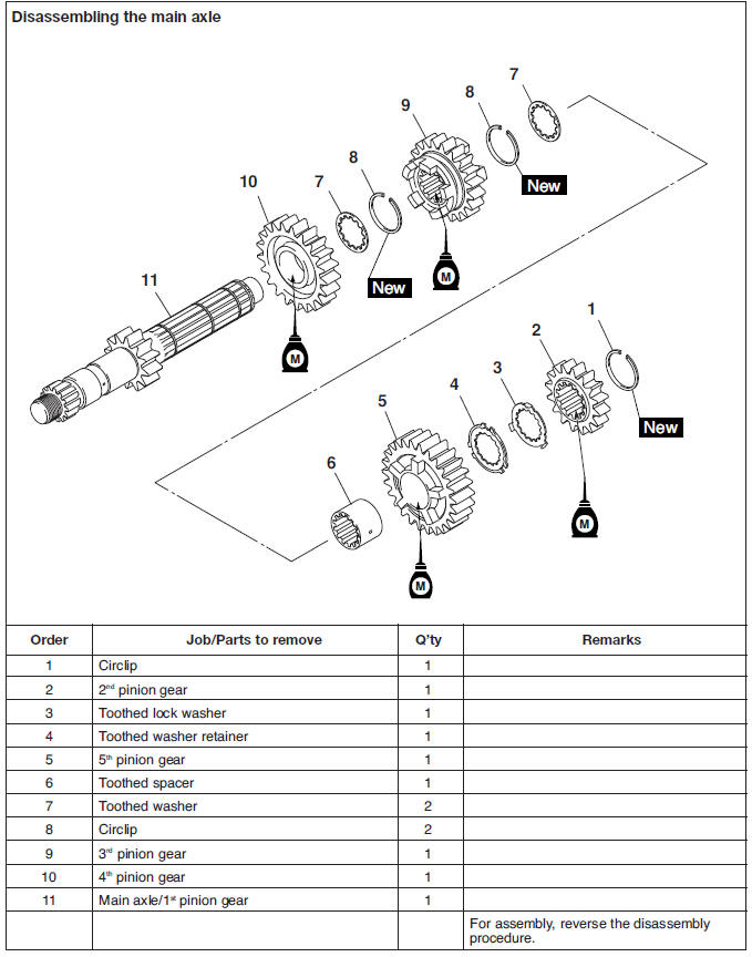
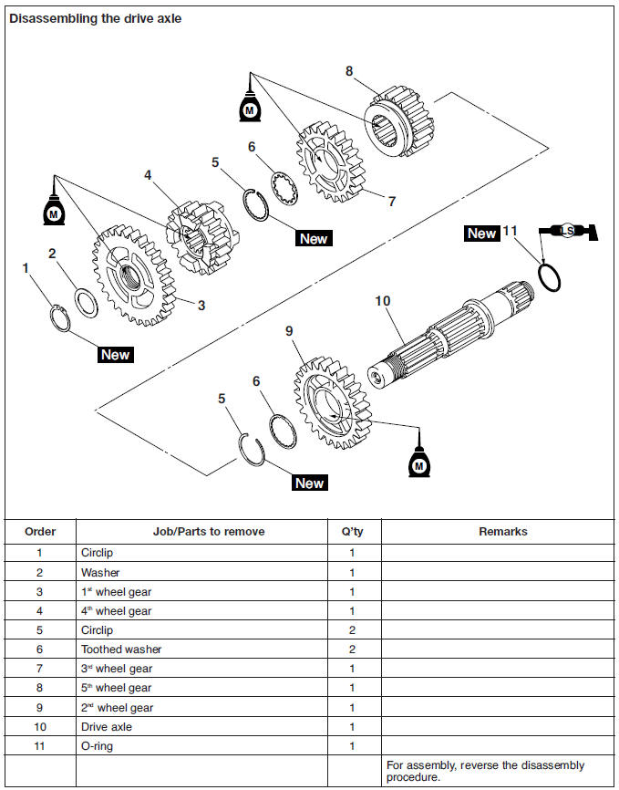
Assembling the main axle and drive axle
1. Install:
- Toothed washer "1"
- Circlip "2"

NOTE:
- Be sure the circlip shape-edged corner "a" is positioned opposite side to the toothed washer and gear.
- Install the circlip so that both ends "b" are positioned in the center of each axle spline "c".
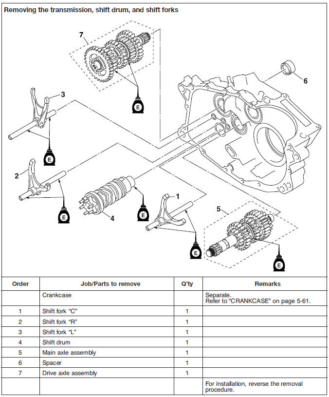
Installing the transmission
1. Install:
- Shift fork "L" "1" (to drive axle)
- Shift fork "C" "2" (to main axle)
- Shift fork "R" "3" (to drive axle)
- Shift drum "4"
- Transmission assembly
NOTE:
- The embossed marks on the shift forks should face towards the right side of the engine and be in the following sequence: "R", "C", and "L".
- Make sure that the shift fork cam follower is properly seated in the shift drum groove.
2. Check:
- Shift operation.
Unsmooth operation → Repair.
NOTE:
- Apply engine oil to each gear and bearing thoroughly.
- Before assembling the crankcase, make sure that the transmission is in neutral and that the gears turn freely.
See also:
 Yamaha MT-03 - Service manual > Cooling system
Radiator Checking the radiator 1. Check: Radiator fins
 Benelli Imperiale 400
 BMW F900XR
 Honda CB500X
 KTM 390 Adventure
 Triumph Street Triple S
 Yamaha MT-03
 Kawasaki Z400
 Triumph Street Triple S
 Yamaha MT-03