 Triumph Street Triple S - Service manual > Crankcases
Caution: The upper and lower crankcases are machined as a matched set and must never be assembled to non-matching halves. Doing so may cause seizure of the engine.
1. Remove the engine from the frame.
2. Remove the sump.
3. Remove the engine covers.
4. Remove the clutch.
5. Remove the oil pump.
Disassembly
Caution: Failure to follow the correct screw release sequence may result in permanent crankcase damage.
1. Invert the engine to give access to the lower crankcase bolts.
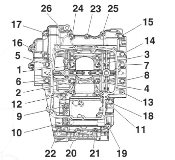
2. Release the lower crankcase bolts in the sequence shown in the diagram below. Note the position of the hardened washers under bolts 19 to 26.
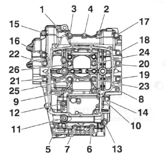
Crankcase Bolt Release Sequence
3. Separate the lower and upper crankcases ensuring that the 3 locating dowels remain in the upper crankcase.
Caution: Do not use levers to separate the upper and lower sections of the crankcase or damage to the crankcases could result.
Note:
- At this point the transmission shafts, balancer, crankshaft, bearings etc. can be removed.
Note:
- The position of each individual bearing shell prior to removal.
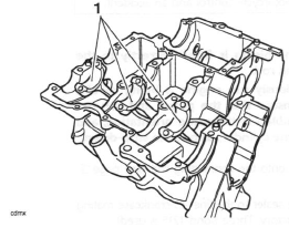
- Collect the piston cooling jets from below the upper main bearings.
Assembly
1. Use high flash-point solvent to clean the crankcase mating faces. Wipe the surfaces clean with a lint-free cloth.
2. Fit the gearbox shafts (if removed), ensuring the locating ring and dowels on the output shaft bearings are positioned correctly in the crankcase.
3. Ensure that the transmission is in neutral.
4. Ensure that the 3 locating dowels are in position in the upper crankcase.
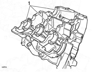
- Locating dowels
5. Apply a thin bead of silicone sealant (At the factory, ThreeBond 1215 is used) to the lower crankcase mating faces.
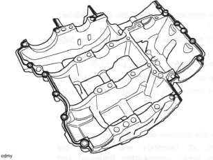
Sealer areas
Caution: Do not use excessive amounts of sealer. The extra sealer may become dislodged and could block the oil passages in the crankcases causing severe engine damage.
6. If removed, insert the three piston cooling jets into the main bearing housings in the upper crankcase.
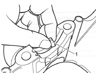
- Piston cooling jet
Caution: Ensure the three piston cooling lets are installed. If the piston cooling jets are omitted, oil pressure will be reduced. Running the engine with low oil pressure will cause severe engine damage.
Note:
- The piston cooling jet for number 3 cylinder is longer and has a larger diameter drilling than the piston cooling jets for number 1 and 2 cylinders. It can also be identified by its smaller outside diameter and a groove around its circumference. Piston cooling jets cannot be installed incorrectly.
7. Install and lubricate the crankshaft bearing shells with clean engine oil (see bearing selection before proceeding).
8. Lubricate the crankshaft journals with clean engine oil.
9. Position the lower crankcase to the upper. An assistant may be required to support the crankcase during alignment.
10. Fit the screws into the lower crankcase and hand tighten until the bolt heads are near contact with the crankcase. Note the position of the hardened washers under bolts 1 to 8.
Note:
- The crankcase screws are tightened in stages.
- Two different sizes of crankcase screw are used. All screws are tightened through the first stage of the tightening procedure but only the M8 size screws are tightened at the second stage.
Caution: Failure to follow the correct screw tightening sequence may result in permanent crankcase damage.
Stage 1 - all screws
1. In the sequence shown below, tighten all crankcase screws to 12 Nm.
Crankcase Bolt Tightening Sequence
Stage 2 - M8 screws only
1. In the correct sequence, tighten only the M8 size crankcase screws (numbers 1 to 8) to 32 Nm.
2. In the correct sequence, tighten only the M8 size crankcase screws (number 9 to 14) to 32 Nm.
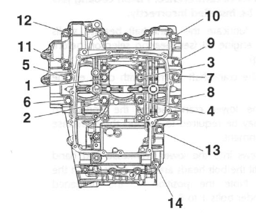
M8 Crankcase Bolt Tightening Sequence
3. Rotate the crankshaft clockwise. Check for tight spots and rectify as necessary.
4. Refit the oil pump.
5. Refit the clutch.
6. Refit the engine covers.
7. Refit the sump.
8. Install the engine in the frame.
Crankshaft
Removal
1. Remove the alternator rotor from the crankshaft.
2. Separate the two halves of the crankcase.
3. Remove the connecting rods.
4. Remove the camshaft drive chain.
5. Release and remove the crankshaft from the upper crankcase.
Note:
- Identify the location of each bearing shell.
- Remove all bearings and inspect for damage, wear, overheating (blueing) and any other signs of deterioration. Replace the bearings as a set if necessary.
- Collect the piston jets from below the upper main bearings.
- If the camshaft drive chain sprocket is removed from the crankshaft for any reason, always install a new fixing. Tighten to 27 Nm.
6. Remove the balancer.
Installation
Caution: Always check the bearing journal clearance, before final assembly of the crankshaft. Failure to correctly select crankshaft bearings will result in severe engine damage.
1. If removed, insert the three piston cooling jets into the main bearing housings in the upper crankcase.
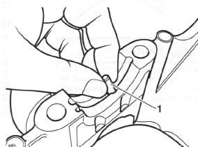
- Piston cooling jet
Caution: Ensure the three piston cooling jets are installed. If the piston cooling jets are omitted, oil pressure will be reduced. Running the engine with low oil pressure will cause severe engine damage.
Note:
- The piston cooling jet for number 3 cylinder is longer and has a larger diameter drilling than the piston cooling jets for number 1 and 2 cylinders. It can also be identified by its smaller outside diameter and a groove around its circumference. Piston cooling jets cannot be installed incorrectly.
2. Select and fit new main and big end shell bearings using the selection processes detailed later in this section.
- Big end shells
3. Lubricate all bearings with a 50/50 solution of engine oil and molybdenum disulphide grease.
4. Ensure that the crankshaft is clean, and that the oil ways within the crank are clean and free from blockages and debris.
5. Refit the balancer.
6. Install the crankshaft ensuring that the crank pins align with the big ends and that the crankshaft and balancer gear markings align as shown in the next illustration.
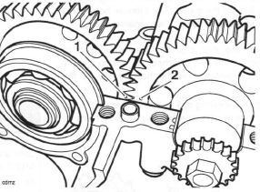
- Balancer backlash and drive gear markings
- Crankshaft markings
7. Refit the connecting rods.
8. If removed, refit the transmission shafts.
9. Assemble the crankcases.
10. Assemble the alternator rotor.
11. Refit the camshaft drive chain.
See also:
 Triumph Street Triple S - Service manual > Crankshaft, Connecting Rods and Pistons
Exploded View - Crankshaft, Connecting Rod, Piston and Liner
Triumph Street Triple S - Service manual > Connecting Rods
Removal Connecting rods may be removed from the engine after first removing it from the frame. The cylinder head must be removed and the crankcase halves separated.
 Benelli Imperiale 400
 BMW F900XR
 Honda CB500X
 KTM 390 Adventure
 Triumph Street Triple S
 Yamaha MT-03
 Kawasaki Z400
 Triumph Street Triple S
 Yamaha MT-03