 Kawasaki Z400 - Service manual > Charging System
Alternator Cover Removal
- Drain: Engine Oil (see Engine Oil Change in the Periodic Maintenance chapter)
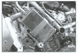
- Remove: Battery Case Cover (see Battery Case Cover Removal in the Frame chapter) Canister Bracket Bolts [A] (Equipped Models)
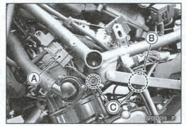
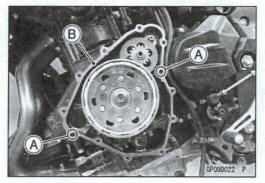
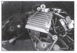
- Disconnect the alternator lead connector [A] and crankshaft sensor lead connector [B].
- Clear each lead [C].
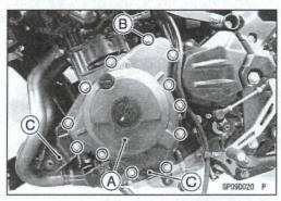
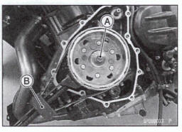
- Place a suitable container under the alternator cover [A].
- Remove: Alternator Cover Bolts [B] Brackets [C] Alternator Cover Gasket Dowel Pins
Alternator Cover installation
- Using a high flash-point solvent, dean off any oil or dirt that may be on the liquid gasket coating area. Dry them with a dean cloth.
- Apply liquid gasket to the alternator lead grommet and crankcase halves mating surface [A] on the front and rear sides of the cover mount.
Sealant - Liquid Gasket, TB1211F: 921044004
Replace the alternator cover gasket with a new one.
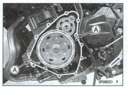
Install the dowel pins [A] and new gasket [B] on the crankcase.
- Install the alternator cover [A] and brackets [B].
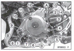
- Tighten the alternator cover bolts following the specified tightening sequence [1 - 14].
L = 35 mm (1.4 in.) [1, 2]
L = 28 mm (1 .1 in.) [except 1,2]
Toque -Alternator Cover Bolts: 9.8 N-m (1.0 kgf*m, 87 In*lb)
- Run the leads correctly (see Cable, Wire, and Hose Routing section in the Appendix chapter).
- Install the removed parts (see appropriate chapters).
Stator Coil Removal
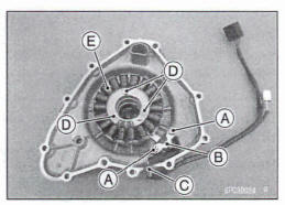
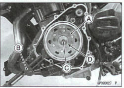
- Remove: Alternator Cover (see Alternator Cover Removal) Crankshaft Sensor Screws [A] Crankshaft Sensor [B] Lead Grommet [C] Stator Coil Bolts [D] Stator Coil [E]
Stator Coil Installation
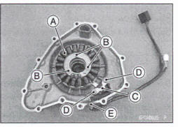
- Install the stator coil [A].
- Apply a non-permanent locking agent to the threads of the stator mil bob [B] and tighten them .
Torque -Stator Coil Bolts: 12 Nm (1.2 kgf-m, 106 in*lb)
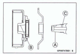
Install the crankshaft sensor [C].
When installing the sensor which is fastened by screws, tighten the screws after placing the sensor on the bottom surface completely
- Apply a non-permanent locking agent b the threads of the crankshaft sensor screws [D] and tighten them.
Torque - Crankshaft Sensor Screws: 5.2 N*m (0.53 kgf-m, 46 in*lb)
- Using a high flash-point solvent, dm off any oil or dirt that may be on the liquid gasket coating area. Dry them with a clean cloth.
- Apply liquid gasket to the circumference of the alternator lead grommet [E], and fit the grommet into the notch of the cover securely.
Sealant- Liquid Gasket, TB1211F: 92104-0004
- Install the alternator cover (see Alternator Cover Installation).
Alternator Rotor Removal
- Remove: Alternator Cover (see Alternator Cover Removal) Shaft [A] Starter Idle Gear [B]
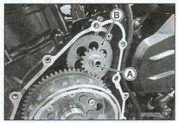
- Hold the alternator rotor [A] firmly with the flywheel holder [B].
Special Tool - Flywheel Holder: 57001 -1313
NOTlCE
Do not hold the alternator rotor using the projections at outside of the rotor.
- Remove the rotor bolt [C] and washer [D].
- Using the flywheel puller [A], remove the alternator rotor [B] from the crankshaft.
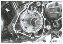
Special Tool - Flywheel Puller Assembly, M38 x 1.5/M35 x 1.5: 57001-1405
- Remove: Woodruff Key [A] Starter Clutch Gear [B]
Alternator Rotor Installation
- Using a cleaning fluid, dean off any oil or dirt on the following
portions and dry them with a clan cloth.
Crankshaft Tapered Portion [A] Alternator Rotor Tapered Portion [B]
- Apply a thin coat of molybdenum disulfide grease to the crankshaft [C].
- Install the starter clutch gear [A].
- Again, clean the crankshaft tapered portion and dry there.
- Fit the woodruff key [B] securely in the slot in the crankshaft before installing the alternator rotor.
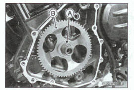
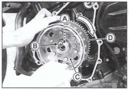
- Align the woodruff key [A] on the crankshaft with the key way [B] in the alternator rotor [C].
- Install the alternator rotor while turning the starter clutch gear [D] clockwise until it engaged into the starter clutch case.
- Using a cleaning fluid, dean off any oil or dirt on the following
areas and dry them with a dean cloth.
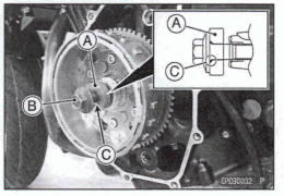
Both Sides of the Washer [A] Threads and Seating Area of the Alternator Rotor Bolt [B] Threads in the Crankshaft End
- Apply molybdenum disulfide oil solution to the threads of the alternator rotor bolt and both sides of the washer.
- Install the washer with its chamfer [C] side facing out.
- Install the rotor bolt and tighten it lightly.
NOTICE
To avoid damaging the components by improperly fitting, make sure that the starter clutch gear turn clockwise freely with the rotor bolt tightened lightly.
If the starter clutch gear becomes binding or turns hardly, reinstall it.
NOTE
Confirm the alternator rotor fit or not to the crankshaft before tightening A with specified torque.
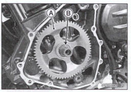
- Tighten the rotor bolt [A] with 55 N-m (5.6 kgf-m, 41 ft-lb) of toque.
Special Tool - Flywheel Holder [B]: 57001-1313
NOTICE
Do not hold the alternator rotor using the projections at outside of the rotor.
- Remove the rotor bolt and washer.
- Check the tightening torque with flywheel puller [A].
Special Tool - Flywheel Puller Assembly, M38 x 1.5/M35*1.5: 57001-1405
*If the rotor is not pulled out with 20 N-m (2.0 kgf*m, 15 ft-lb) of drawing torque, it is installed correctly.
*If the rotor is pulled out with under 20 N-m (2.0 kgf*m, 15 ft-b) of drawing torque, dean off any oil dirt or flaw of the crankshaft and rotor tapered portion, and dry them with a dean doth. Then, confirm that it is not pulled out with above torque.
- Tighten the alternator rotor bolt while holding the alternator rotor firmly with the flywheel holder
Specia1 Tool - Flywheel Holder: 57001 -1313
NOTICE
Do not hold the alternator rotor using the projections at outside of the rotor.
Torque -Alternator Rotor Bolt: 80 Nm (8.2 kgf*m, 59 ft-lb)
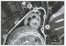
- Apply a thin coat of molybdenum disulfide grease to the shaft [A], and install it and starter idle gear [B].
- Install the alternator cover (see Alternator Cover Installation).
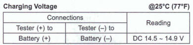
Carding Voltage Inspection
Check the battery condition (see Charging Condition Inspection).
Warm up the engine to obtain actual alternator operating conditions.
Remove the front seat (see Front Seat Removal in the Frame chapter).
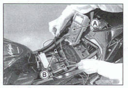
Check that the ignition switch is turned off, and connect a tester [A] to the battery terminals [B]
Start the engine, end note the voltage readings at various
engine speeds (except Idling engine speed) with the
headlight turned on and then turned off (To turn off the headlight, disconnect
the headlight connector on the headlight unit). The readings should show
nearly battery voltage when the engine speed is low, and, as the engine
sped rises, the rsadkng3 should also rise. But they must
be kept under the specified voltage.
- Turn off the ignition switch to stop the engine, and disconnect a tester.
*If the charging voltage is kept Between the values given in the table, the charging system Is considered to be working normally.
*If the charging voltage is much higher than the values specified in the table, the regulator/ rectifier is defective or the regulator/rectifier leads are loose or open.
If the charging voltage does not rise as the engine speed increases, then the regulator/rectifier is defective or the alternator output is insufficient for the loads. Check the alternator and regulator/rectifier determine which part is defective.
Alternator Inspection
There are three types of alternator failures: short, open (wire burned out), or loss in rotor magnetism. A short or open in one of the coil wires will result in either a low output, or no output at all. A loss in rotor magnetism, which may be caused by dropping or hitting the alternator, by leaving it near an electromagnetic field, or just by aging, will result in low output.
- To check the alternator output voltage, do the following procedures
- Turn the ignition switch off.
- Remove the left middle fairing (see Middle Fairing Removal in the Frame chapter).
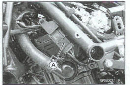
- Remove the canister bracket bolts (equipped models).
- Disconnect the alternator lead connector [A].
- Connect a tester as shown in the table 1.
- Start the engine.
- Run it at the rpm given in the table 1.
- Note the voltage readings (total 3 measurements).
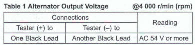
*If the output voltage shows the value in the table, the alternator operates properly.
*If the output voltage shows a much lower reading than that given in the table, stop the engine and inspect the stator coil resistance.
- Check the stator coil resistance as follows.
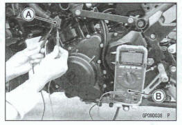
- Stop the engine.
- Disconnect the alternator lead connector [A].
- Connect a tester [B] as shown in the table 2.
- Note the readings (total 3 measurements).
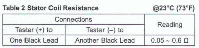
- When measuring the resistance, use a tester that can measure the standard value.
*If there is more resistance than shown in the table, or no tester reading (infinity) for any two leads, the stator has an open lead and must be replaced. Much less than this resistance means the stator is shorted, and must be replaced.
- Measure the resistance between each of the black lead and chassis ground.
*Any tester reading less than infinity ( )
indicates a short,
necessitating stator replacement.
)
indicates a short,
necessitating stator replacement.
*If the stator coils have normal resistance, but the voltage check showed the alternator to be defective; then the rotor magnets have probably weakened, and the rotor must be replaced.
Regulator/Rectifier Removal
- Remove: Left Middle Fairing (see Middle Fairing Removal in the Frame chapter) Regulator/ Rectifier Bolts [A]
- Disconnect the connector [B] and remove the regulator/rectifier [C] .
Regulator/Rectifier Installation
- Installation is the reverse of removal.
- Tighten: Torque - Regulator/Rectifier: 9.8 N-m (1.0 kgf*m, 87 In-lb)
- Install the removed parts (see appropriate chapters).
Regulator/Rectifier Inspection
- Refer to the Charging System Troubleshooting for the Regulator/Rectifier Inspection.
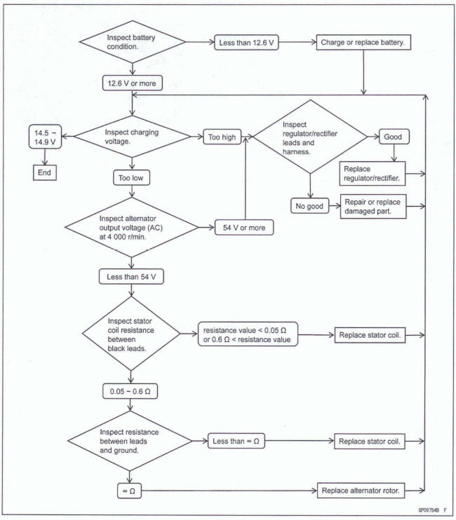
Charging System Troubleshooting
- Before inspection, remove all accessories that consume electrical power
NOTE
Even when the charging system is working properly, the battery may discharge if the motorcycle is equipped with too many accessories.
- Pay attention to riding conditions and the customer's riding habits which could affect the charging system such as:
Frequent use at low engine speed Frequent and unnecessary brake pedal dragging → Battery Discharged
- Recharge the battery if it is discharged.
Charging System Circuit
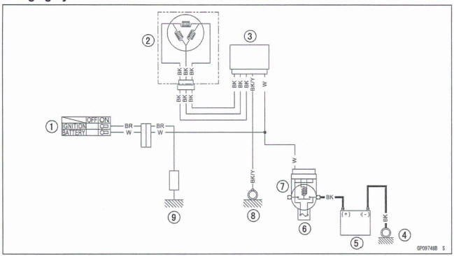
- Ignition Switch
- Alternator
- Regulator/Rectifier
- Engine Ground
- Battery
- Main Fuse 30 A
- Starter Relay
- Frame Ground (3)
- Load
See also:
 Kawasaki Z400 - Service manual > Battery
Battery Removal Turn the ignition switch off. Remove: Front Seat (see Front Seat Removal in the Frame chapter) Disconnect the negative (-) cable [A].
Kawasaki Z400 - Service manual > Ignition System
Crankshaft Sensor Peak Voltage Inspection NOTE
 Benelli Imperiale 400
 BMW F900XR
 Honda CB500X
 KTM 390 Adventure
 Triumph Street Triple S
 Yamaha MT-03
 Kawasaki Z400
 Triumph Street Triple S
 Yamaha MT-03