 Kawasaki Z400 - Service manual > Ignition System
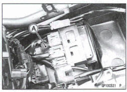
Crankshaft Sensor Peak Voltage Inspection
NOTE
Be sure the battery is fully charged.
- Remove: Battery Case Cover (see Battery Case Cover Removal in the Frame chapter)
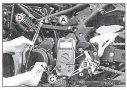
- Disconnect the crankshaft sensor lead connector [A].
- Using a tester [B] and peak voltage adapter [C], measure crankshaft sensor peak voltage at the connector.
Special Tools - Peak Voltage Adapter: 57001 -1415 Type: KEK-54-9-B Needle Adapter Set [D]: 57001- 1874
Connections: 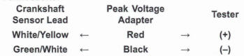
- Temporarily install the battery (see Battery Installation).
- Turn the ignition switch and engine stop switch on.
- Pushing the starter button, turn the engine 4 - 5 seconds with the transmission gear in neutral to measure the crankshaft sensor peak voltage.
- Repeat the measurement 5 or more times.
Crankshaft Sensor Peak Voltage Standard: 5.4 V or more
*If the tester reading is not specified one, inspect the crankshaft sensor (see Crankshaft Sensor Inspection).
Stick Coil Removal
NOTICE
Never drop the stick coils especially on a hard surface.
Such a shock to the stick coils can damage It.
- Remove: Air Cleaner Housing (see Air Cleaner Housing Removal in the Fuel System (DFI) chapter)
- Disconnect the stick coil connectors [A].
- Pull the stick coils [B] off the spark plugs.
NOTICE
Do not pry the connector part of the coil while removing the coil.
Stick Coil Installation
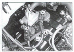
- Insert the stick coils [A] so that the coil heads align with the lines [B] on the cylinder head cover.
NOTICE
Do not tap the coil head while installing the coil.
- After installation, be sure the stick, coils are installed securely by pulling up them lightly.
- Run the leads correctly (see Cable, Wire, and hose Routing section in the Appendix chapter).
- Install the removed parts (see appropriate chapters).
Stick Coil Inspection
- Remove the stick coils (see Stick Coil Removal).
- Measure the primary winding resistance [A] as follows.
Connect a tester between the coil terminals.
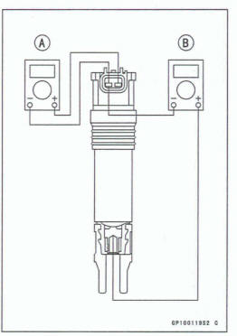
- Measure the secondary winding resistance [B] as follows.
Connect the tester between the plug terminal and (-) coil terminal.
Stick Coil Winding Resistance
Primary Windings: 1.11 - 1.50
 20ºC (68ºF)
Secondary Windings: 6.4 - 9.6 k
20ºC (68ºF)
*If the tester does not read as specified, replace the coil.
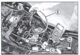
Suck Coil Primary Peak Voltage Inspection
NOTE
Be sure the battery is fully charged.
- Remove the stick coils (see Stick Coil Removal), but do not remove the spark plugs.
- Measure the primary peak voltage as follows.
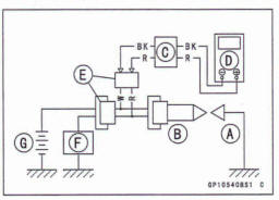
- Install the new spark plug [A] into each stick coil [B], and ground them onto the engine.
- Connect the peak voltage adapter [C] into a tester [D].
- Connect the adapter to the lead wire-peak voltage adapter [a whid.1 is connected between the stick mil connector and stick mil.
ECU [F] Battery [G]
Special Tools - Peak Voltage Adapter 57001 -1415
Type: KEK-54-9-B
Lead Wire - Peak Voltage Adapter: 57001-1449
Primary Lead Connection
Adapter (R, +) to lead wire-peak voltage adapter (R)
Adapter (BK, -) to had wire-peak voltage adapter (W)
WARNING
To avoid extremely high voltage shocks, do not touch the spark plugs or tester connections.
- Turn the ignition switch and engine stop switch on.
- Pushing the starter button, turn the engine 4 - 5 seconds with the transmission gear in neutral to measure the primary peak voltage.
- Repeat the measurements 5 times for one stick coil.
*If the reading is less than the specified value, check the following.
Stick Coils (see stick Coil Inspection) Crankshaft Sensor (see Crankshaft Sensor Inspection) ECU (see ECU Power Supply Inspection in the Fuel System (DFI) chapter)
Spark Plug Removal
- Refer to the Spark Plug Replacement In the Periodic Maintenance chapter.
Spark Plug installation
- Refer to the Spark Plug Replacement in the Periodic Maintenance chapter.
Ignition system
Spark Plug Condition Inspection
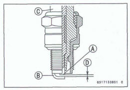
- Remove the spark plugs (see Spark Plug Replacement in the Periodic Maintenance chapter).
- Usually inspect the spark plugs.
*If the spark plug center electrode [A] and/or side electrode [B] are corroded or damaged, or if the insulator [C] is cracked, replace the plug.
*If the spark plug is dirtied or the carbon is accumulated, replace the spark plug.
- Measure the gap [D] with a wire-type thickness gauge.
*If the gap is incorrect, replace the spark plug.
Spark Plug Gap: 0.7 - 0.8 mm (0.028 - 0.031 In.)
- Use the standard spark plug or its equivalent.
Spark Plug: NGK LMAR9G
Interlock Operation Inspection
- Raise the rear wheel off the ground using the stand (see Rear Wheel Removal in the Wheels/Tires chapter).
- Turn the engine stop switch on (run position).
1st Check
- Start the engine to the following conditions.
Condition:
Transmission Gear→ 1st Position
Clutch Lever → Release
Side Stand → Down or Up
- Turn the ignition switch on and push the starter button.
- Then the starter motor should not turn when the starter system circuit is normality.
*If the engine is start, inspect the starter lockout switch, gear position sensor and relay box.
*If their parts are normality, replace the ECU.
2nd Check
- Start the engine to the following conditions.
Condition: Transmission Gear →1st Position
Clutch Lever→Pulled in
Side Stand → Up
- Turn the ignition switch on and push the starter button.
- Then the starter motor should turn when the starter system circuit is normality.
*If the starter motor is not turn, inspect the starter lockout switch, gear position sensor, side stand switch and relay box.
*If their parts are normality, replace the ECU.
3rd Check
- Inspect the engine for its secure stop after the following operations are completed.
- Run the engine to the following conditions.
Condition: Transmission Gear → 1st Position
Clutch Lever → Pulled in
Side Stand →Up
- Set the side stand on the ground, then the engine will stop.
*If the engine does not stop, inspect the gear position sensor, side stand switch and relay box.
*If their parts are normality, replace the ECU.
IC Igniter Inspection
The IC igniter is built in the ECU [A].
Refer to the following items.
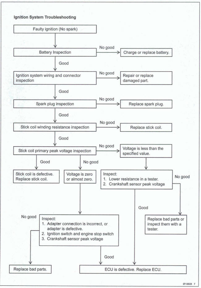
Interlock Operation Inspection (see Interlock Operation Inspection) Ignition System Troubleshooting (see Ignition System section) ECU Power Supply Inspection (see ECU Power Supply Inspection in the Fuel System (DFI) chapter)
Ignition System Circuit
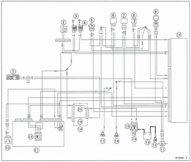
- Ignition Switch
- Engine Stop Switch
- Spark Plugs
- Stick Coils
- Throttle Sensor
- Vehicle- down Sensor
- Gear Position Sensor
- Water Temperature Sensor
- Crankshaft Sensor
- ECU
- Side Stand Switch
- Engine Ground
- Battery
- Main Fuse 30 A
- Starter Relay
- Frame Ground (4)
- Frame Ground (2)
- Fuse Box (1)
- Ignition Fuse 10 A
- ECU Fuse 15 A
- Relay Box
- ECU Main Relay
- Starter Lockout Switch
See also:
 Kawasaki Z400 - Service manual > Charging System
Alternator Cover Removal Drain: Engine Oil (see Engine Oil Change in the Periodic Maintenance chapter) Remove: Battery Case Cover (see Battery Case Cover Removal in the Frame chapter) Canister Bracket Bolts [A] (Equipped Models) Disconnect the alternator lead connector [A] and crankshaft sensor lead connector [B]. Clear each lead [C]. Place a suitable container under the alternator cover [A]. Remove: Alternator Cover Bolts [B] Brackets [C] Alternator Cover Gasket Dowel Pins
Kawasaki Z400 - Service manual > Electric Starter System
Starter Motor Removal NOTICE Do not tap the starter motor shaft or body. Tapping the shaft or body could damage the motor. Remove: Right Middle Fairing (see Middle Fairing Removal in the Frame chapter) Frame Bracket Bolts [A] Right Frame Bracket [B] Slide back the rubber cap [A] and remove the starter motor cable terminal nut [B]. Remove: Starter Motor Mounting Bolts [C] Starter Motor [D]
 Benelli Imperiale 400
 BMW F900XR
 Honda CB500X
 KTM 390 Adventure
 Triumph Street Triple S
 Yamaha MT-03
 Kawasaki Z400
 Triumph Street Triple S
 Yamaha MT-03