 Triumph Street Triple S - Service manual > Camshafts
Removal
1. Remove the camshaft drive chain tensioner.
Note:
- It is not necessary to remove the camshaft drive chain completely.
- Each camshaft and sprocket is removed as an assembly.
- Before commencing work, ensure the crankshaft 'dot' mark is in alignment with the line in the crankcase.
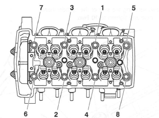
2. Note the orientation of the camshaft ladder in relation to the head.
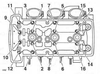
3. Progressively release the bolts securing the camshaft ladder to the head in the sequence shown below.
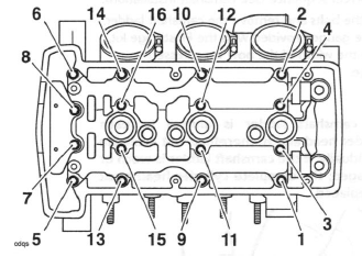
Camshaft Ladder Bolt Release Sequence
4. Remove the camshaft ladder and top pad, and collect the dowels (if loose) and spark plug tower O-rings.
5. Lift the camshaft drive chain from the exhaust camshaft sprocket and remove the exhaust camshaft.
6. Repeat the procedure for the inlet camshaft.
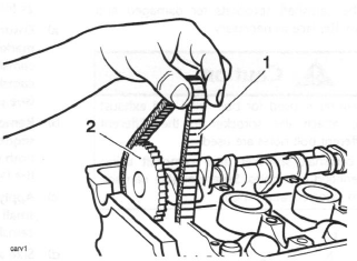
- Camshaft drive chain
- Inlet camshaft
Note:
- The inlet and exhaust camshafts are different. They can be identified by a raised feature in the centre of the exhaust camshaft, which is machined off on the inlet camshaft. The camshafts can be further identified a letter 'I' for inlet or 'E' for exhaust stamped on the end of the sprocket boss.
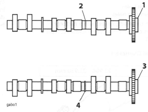
- Inlet camshaft
- Machined section
- Exhaust camshaft
- Raised section
Camshaft and Bearing Cap Inspection
1. Inspect the camshaft sprockets for damaged and worn teeth. Replace as necessary.
Caution: The same sprocket is used for both inlet and exhaust camshafts. To attach the sprocket to the different camshafts, different bolt holes are used.
Never fit a camshaft sprocket to a camshaft using incorrectly identified bolt holes. Severe engine damage will result from incorrect attachment.
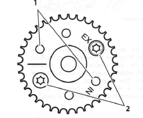
- Inlet camshaft bolt holes
- Exhaust camshaft bolt holes
2. Measure the camshaft journals with a micrometer. If any journal is outside the specified tolerance, replace the camshaft.
Standard Journal Diameters
Standard: 23.900 - 23.930 mm
- Standard journal
3. Examine the camshaft and camshaft ladder for excessive wear and damage.
4. Check the journal-to-head clearances, using 'Plastigage' (Triumph part number 3880150-T0301) as follows:
- Ensuring that the camshaft sprocket alignment marking is located as for removal, assemble one camshaft to the head and progressively tighten the camshaft ladder in the sequence shown overleaf.
- Remove the camshaft ladder using the bolt release sequence given earlier. Wipe the exposed areas of both the camshaft journal and a single cap area of the ladder.
- Apply a thin smear of grease to the journal and a small quantity of silicone release agent to the camshaft cap area of the ladder.
- Size a length of the Plastigage to fit across the camshaft journal. Fit the Plastigage to the camshaft journal using the grease to hold the strip in place.
- Refit the camshaft ladder then evenly and progressively tighten all the camshaft ladder bolts in the correct sequence (see camshaft installation).
- Release the bolts and remove the camshaft ladder.
Using the gauge provided with the Plastigage kit, measure the width of the now compressed Plastigage.
Note:
- The camshaft ladder is unique to each cylinder head and is, therefore, not available individually. If the camshaft ladder is worn or damaged, the complete cylinder head must be replaced.
Measuring the Compressed Plastigage.
5. Calculate the journal clearance using the Plastigage chart supplied with the Plastigage kit.
Camshaft journal clearance
Standard: 0.070 - 0.121 mm
Service limit: 0.170 mm
6. If the clearance measured is within the specified tolerance, remove the ladder and clean off all traces of Plastigage. Assemble the camshafts.
Note:
- If the measured clearance is outside the tolerance, and the camshaft journals are within tolerance, the cylinder head must be replaced.
Caution: Although Plastigage is oil soluble, all traces of the material must be removed to prevent blockage of the oil drillings and resultant engine damage.
Installation
1. Thoroughly clean the camshafts and journals. Inspect the ends of the camshafts for correct fitment of the sealing plugs. Lubricate the camshafts with clean engine oil before fitting to the head.
2. Locate each camshaft to the head ensuring the camshafts are correctly identified (inlet and exhaust) and are also correctly located over their respective valve banks.
3. Working on one camshaft at a time, locate the camshaft drive chain over the camshaft sprocket.
Position the camshaft in the same position as for removal before attempting to fit the ladder (that is, with the timing marks on the camshaft sprockets level and pointing inwards, and with the 'dot' mark on the primary gear in alignment with the line on the crankcase).
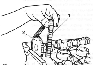
- Camshaft drive chain
- Inlet camshaft
4. Repeat the procedure for the other camshaft.
Caution: If the camshafts and ladder are fitted without first aligning the timing marks on both the crankshaft and camshaft sprockets, the inlet and exhaust valves will contact each other causing damage to both the head and the valves.
5. Lubricate the camshaft bearing areas of the camshaft ladder with a 50/50 solution of engine oil and molybdenum disulphide grease.
6. Assemble the dowels, camshaft ladder and top pad in the same location and orientation as prior to removal.
Note:
- The bolts for the camshaft cap ladder are tightened in stages.
Stage 1
7. Lubricate the threads of the camshaft cap ladder bolts with clean engine oil, then fit and evenly tighten the bolts to 5 Nm, in the sequence shown below.
Camshaft Cap Ladder Bolt Tightening Sequence
Stage 2
8. In the sequence shown above, tighten the bolts to 10 Nm.
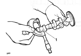
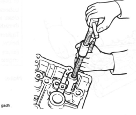
9. Before fitting the camshaft drive chain tensioner, ensure that each camshaft rotates freely using service tool T3880102. Do not rotate either camshaft by more than 5.
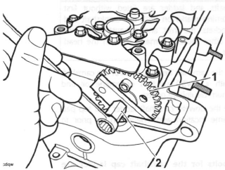
- Exhaust camshaft
- Tool T3880102
Caution: If any components have been renewed, the valve clearances must be checked and adjusted. Running with incorrectly adjusted valve clearances may cause excess engine noise, rough running and engine damage.
10. Refit the camshaft drive chain tensioner.
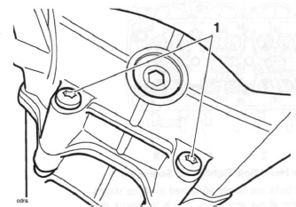
11. Rotate the engine through 4 full revolutions, and reset number 1 cylinder to TDC. Ensure that the 'dot' mark on the primary gear aligns with the line on the crankcase.
- 'Dot' mark
- Marker line
12. Check that the camshaft timing marks align as illustrated below. Rectify any misalignment before proceeding.
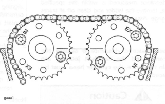
Camshaft to Cylinder Head Alignment Marks
13. Check the valve clearances. Adjust as necessary.
Valve Clearances
Camshaft, valve, valve shim and valve seat wear affects the valve clearances. The effect of this wear is to change the gap between the camshaft and tappet bucket, causing engine noise and improper running. If the valve clearances become too small, permanent damage to the valve and valve seat will take place. If the valve clearance becomes too great, the engine will become noisy and will not run correctly.
Valve Clearance Measurement
Note:
- Valve clearance measurement must be carried out with the engine cold.
1. Remove the camshaft cover.
2. Remove the spark plugs to reduce compression resistance when turning the engine.
3. Select a high gear and, using the rear wheel, turn the engine until a pair of camshaft lobes are positioned pointing away from the valves.
4. Using feeler gauges, measure and record the clearances for this pair of valves only.
5. Repeat the process until the valve clearances for all valves have been checked.
Note:
- If the measurement does not fall within the specified range, adjustment must be made.
- The correct valve clearances are in the range given below:
All models except Daytona 675 from VIN 381275
Inlet: 0.10 - 0.20 mm
Exhaust: 0.275 - 0.325 mm
Daytona 675 from VIN 381275 only
Inlet: 0.10 - 0.20 mm
Exhaust: 0.325 - 0.375 mm
Caution: If the valve clearances are not checked and corrected, wear could cause the valves to remain partly open, which lowers performance, burns the valves and valve seats and may cause serious engine damage.
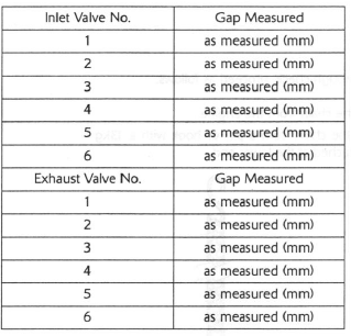
6. Record the measured valve clearances on a chart similar to the example shown.
Typical Valve Clearance Chart
Valve Clearance Adjustment
Note:
- To adjust the valve clearances the camshafts must be removed. Follow the camshaft removal procedure.
1. Remove the camshafts.
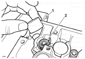
2. Remove the tappet bucket from the cylinder head.
3. Remove the shim from the valve head.
- Tappet bucket
- Shim
Note:
- The shim may withdraw with the tappet bucket.
4. Measure the original shim, using a micrometer and select the appropriate new shim as required.
Clearance too small:
- Fit a thinner shim.
Clearance too large:
- Fit a thicker shim.
Note:
- Shims are available ranging from 1.70 mm to 3.00 mm in increments of 0.025 mm.
5. Fit the new shim to the valve head.
6. Lubricate the tappet bucket(s) with a 50/50 solution of engine oil and molybdenum disulphide grease.
7. Refit the tappet bucket.
8. Refit the camshafts.
9. Re-check all valve clearances.
10. Repeat the procedure if the valves require further adjustment.
Camshaft Drive Chain
Removal
1. Remove the camshafts.
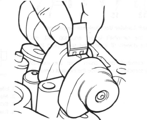
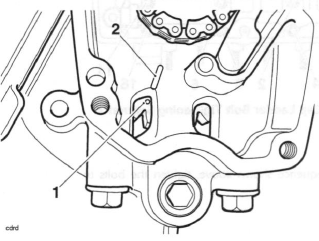
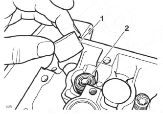
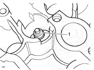
2. Remove the bolt from the centre of the camshaft drive chain housing in the cylinder head.
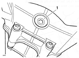
- Centre bolt
3. Raise the front camshaft drive chain rubbing blade and detach the camshaft drive chain from the crankshaft gear.
4. The camshaft drive chain is removed from inside the head-space.
Inspection
Visual in-situ checks can also be made as follows:
1. Check for significant blue discolouration of the chain plates indicating excessive heat build-up.
2. Examine all pins for signs of rotation.
3. Check for cracking or deep scratching of the chain plates.
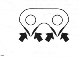
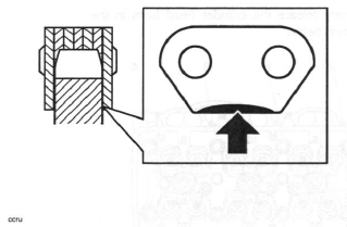
4. Check for severe wear of the inner plates as indicated in the diagram below.
For a more thorough check, proceed as follows:
1. Remove the chain from the engine.
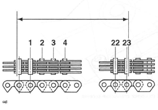
2. Suspend the chain from a pin or hook with a 13kg weight attached at the lower end.
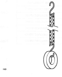
3. Measure across 23 links as shown in the diagram below. If the chain is within limits, the measurement should be no longer than 149.48 mm.
Measurements beyond 149.48 mm indicate that the chain must be replaced.
4. Check for severe wear of the inner surface of the outer plates at the side-contact points with the sprocket teeth.
5. Check for signs of stiffness or kinking.
6. Check for severe wear of the plates in the area shown below.
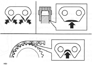
If any of these symptoms are evident, the camshaft drive chain must be replaced.
Installation
1. Fit the camshaft drive chain and locate the lower end around the crankshaft gear.
2. Incorporating a new seal, refit the bolt to the centre of the camshaft drive chain housing in the cylinder head, tightening to 12 Nm.
3. Refit the camshafts.
Cylinder Head
Removal
Note:
- Removal of the cylinder head is not possible with the engine in the frame.
1. Remove the engine from the frame.
2. Remove the camshafts.
3. Remove the camshaft drive chain.
4. Remove the camshaft drive chain tensioner blades.
5. Note the position of all tappet buckets and shims such that they can be refitted in the same positions.
Remove all the tappet buckets and shims.
- Tappet bucket
- Shim
Note:
- To prevent the tappet buckets and shims from becoming mixed, place the shim and tappet together in a marked container. The components must be refitted in their original positions.
6. Disconnect the coolant bypass hose from the rear of the cylinder head.
7. Release the screws securing the outside of the cylinder head to the upper crankcase.
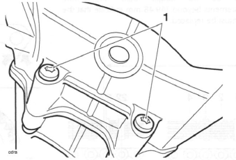
- Cylinder head to upper crankcase screws
Note:
- Up to engine number 327506, the cylinder head bolts are coloured grey.
- From engine number 327507, the cylinder head bolts sliver coloured bolt and are fitted with a hardened washer.
8. Progressively release the cylinder head bolts in the order shown below.
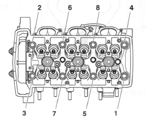
Cylinder Head Bolt Release Sequence
9. Lightly tap the cylinder head with a rubber mallet to break the seal of the gasket.
10. Remove the cylinder head. Discard the cylinder head bolts and gasket.
Inspection
1. Thoroughly clean the surface of the head and check for damage and pitting of the combustion chambers.
2. Using a straight edge, check the cylinder head gasket face for warp which could lead to gasket failure. Replace the head if warped.
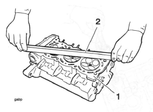
- Cylinder head gasket face
- Straight edge
3. Check the camshaft drive chain tensioner blades.
Renew if worn or damaged.
Installation
1. Thoroughly clean the upper faces of the crankcase, taking care not to damage the mating surfaces.
2. Fit a new cylinder head gasket ensuring that the head to crankcase location dowels are correctly in place.
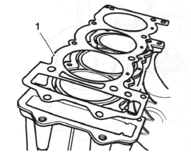
- Cylinder head gasket
3. Ensure that the cylinder head face is completely clean.
4. Carefully lower the cylinder head over the camshaft drive chain and locate the head onto the dowels.
Caution: Using the correct procedure to fit and tighten the cylinder head bolts will ensure the long term reliability of the cylinder head gasket.
Clean each bolt, paying particular attention to the threads and under-bolt-head areas. If any of the threads or bolt-head areas are damaged, replace the bolt(s).
Lubricate the threads with engine oil, and then wipe clean with a lint-free cloth leaving minimal oil on the threads (that is, almost dry to touch).
Tighten the bolts using the three-stage procedure given below.
Failure to observe these important items may lead to engine damage through a damaged head gasket.
Note:
- Up to engine number 327506, new cylinder head bolts and washers must be fitted.
- From engine number 327507, new cylinder head bolts must be fitted with the original washers.
5. Fit new bolts and washers to the head and tighten until finger tight.
6. The cylinder head bolts must be tightened in the following sequence:
Cylinder Head Bolt Tightening Sequence
7. The head bolts are finally tightened in three stages, all using the above sequence. This is to ensure that the cylinder head gasket seals correctly to the head and crankcase. The three stages are as follows:
Note:
- For stages A and B of the head bolt tightening operation, a torque wrench of known, accurate calibration must be used.
- Tighten the head bolts, in the sequence shown above, to 15 Nm.
- Tighten the head bolts in the sequence shown on the previous page, to 20 Nm.
- For the final torque operation, Stage C, (see below) which is carried out in the sequence shown on the previous page, a 'torque turn' method is used. The bolts must be turned through 120º to reach the final setting. To accurately gauge the 120 0 turn, use service tool 3880105-T0301 as follows:
- Fit the tool between the Torx socket and the drive handle
and locate the Torx drive to the head bolt. Pick an increment point on the
torque turn gauge which aligns with a suitable reference point on the head.
Tighten the bolts until 12 of the 10º (I.E. 120º) gauge increments have rotated past the chosen point on the head.
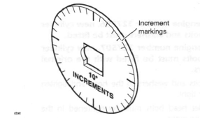
Tool T3880105-T0301
6. Fit the screws securing the side of the cylinder head to the crankcase and tighten to 10 Nm.
- Cylinder head to upper crankcase screws
7. Install the camshaft drive chain tensioner blades.
8. Clean and lubricate the tappet buckets with a 50/50 solution of engine oil and molybdenum disulphide grease and refit the buckets and shims in the same locations from which they were removed.
9. Refit the camshaft drive chain.
10. Refit the camshafts.
11. Install the engine to the frame.
Valves and Valve Stem Seals
Removal from the Cylinder Head
1. Remove each valve from the head using a valve spring compressor. The compressor must act on the top cup to allow removal of the valve collets.
Valve removal
2. Once the collets are released, remove the following items:
- valve spring retainer
- valve spring
- valve spring base
- valve stem oil seal
- valve (de-burr before removal)
- Valve stem seal
Note:
- Ensure inlet and exhaust valve components do not become mixed.
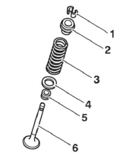
- Collets
- Valve spring retainer
- Valve spring
- Valve spring base
- Valve stem oil seal
- Valve
Installation
1. Lubricate the valve stems with a 50/50 solution of engine oil and molybdenum disulphide grease.
2. Install the valve into the valve guide and refit the spring base to the valve spring recess in the head.
3. Fit the valve stem seal over the valve stem and, using a suitable tool, press down fully until the seal is correctly seated over the valve guide.
Note:
- During fitment of the valve stem seal, two distinctly different degrees of resistance will be noted when the seal is correctly fitted.
- Firstly, press the seal down the valve stem until the lower side of the seal comes into contact with the valve guide. Greater resistance is felt at this contact point and further gentle pressure is then required to locate the seal over the top end of the valve guide.
- On application of this pressure, the seal can be felt to positively locate over the top face of the valve guide. Once correctly positioned, the seal cannot be pushed down any further.
Caution: Incorrect fitment of the valve stem oil seals could lead to high oil consumption and blue smoke emissions from the exhaust system. Do not use excessive force in fitting the seal as this may break th e seal ring.
4. Install the valve spring over the valve stem. Ensure the close wound, colour coded ends of the springs are fitted downwards (towards the piston).
5. Fit the valve spring retainer.
6. Compress the valve spring ensuring that the spring is compressed squarely to prevent damage to the valve stem and cylinder head.
7. Fit the valve collets ensuring correct collet location in the spring retainer and valve as the spring compressor is released.
Caution: Always check for correct location of the valve collets during and after assembly. If not fitted correctly, the collets may become dislodged when the engine is running allowing the valves to contact the pistons. Any such valve to piston contact will cause severe engine damage.
Valve to Valve Guide Clearance
If the valve guides are worn beyond the service limit given below, the cylinder head must be replaced.
Valve Stem to Guide Clearance
Inlet: 0.010 - 0.040 mm
Service limit 0.078 mm
Exhaust: 0.030 - 0.060 mm
Service limit 0.098 mm
Valve Guides
If a valve guide is found to be worn beyond the service limit, the complete cylinder head must be renewed.
Valve Face Inspection
Remove any carbon build-up from the valve head area.
Examine the valve seat face, checking in particular for signs of cracking or pitting.
See also:
 Triumph Street Triple S - Service manual > Camshaft Drive Chain Tensioner - all Models
Removal 1. Remove the camshaft cover. 2. Noting the position of the bolt fitted with the copper washer, remove the right hand crank cover. Discard the gasket. Right hand crank cover Copper washer position
Triumph Street Triple S - Service manual > Clutch
Exploded View - Clutch Cover Exploded View - Clutch Assembly
 Benelli Imperiale 400
 BMW F900XR
 Honda CB500X
 KTM 390 Adventure
 Triumph Street Triple S
 Yamaha MT-03
 Kawasaki Z400
 Triumph Street Triple S
 Yamaha MT-03