 Triumph Street Triple S - Service manual > Camshaft Drive Chain Tensioner - all Models
Removal
1. Remove the camshaft cover.
2. Noting the position of the bolt fitted with the copper washer, remove the right hand crank cover. Discard the gasket.
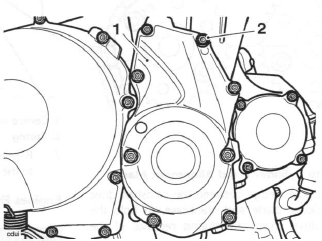
- Right hand crank cover
- Copper washer position
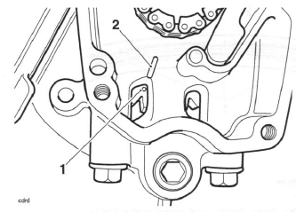
3. Rotate the crankshaft clockwise (the normal direction of rotation), using the bolt fitted to the end of the crankshaft. Stop rotation when number 1 cylinder is at top dead centre (TDC), that is when the 'dot' mark on the primary gear aligns with the line on the crankcase.
- 'Dot' mark
- Marker line
Note:
- In addition to the 'dot' mark alignment, at TDC, the alignment marks on the camshaft sprockets will point inwards at a point level with the joint face.
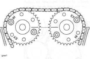
Camshaft to Cylinder Head Alignment Marks
4. Place a suitable wedge between the camshaft drive chain tensioner blade and crankcase, to hold the camshaft drive chain taut during removal of the tensioner.
5. The Daytona 675 from VIN 381275 has a hydraulic tensioner. All other models have a spring loaded tensioner.
For engines fitted with the spring loaded tensioner, continue from step 6 to 7.
For engines fitted with the hydraulic tensioner, continue from step 8 to 9.
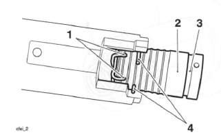
Engines Fitted with the Spring Loaded Tensioner
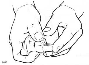
Warning: The tensioner centre nut is under spring tension. Always wear hand, eye and face protection when withdrawing the centre nut and take great care in order to minimise the risk of injury and loss of components.
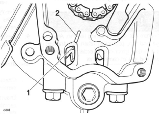
6. Carefully remove the centre nut from the tensioner and withdraw the tensioner spring.
- Centre nut
- Spring
7. Remove and discard the bolts securing the tensioner to the cylinder head. Remove the tensioner.
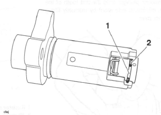
Engines Fitted with the Hydraulic Tensioner
Warning: The hydraulic tensioner is under spring tension. Always wear hand, eye, and face protection when withdrawing the tensioner mounting bolts and take great care to minimise the risk of injury and loss of components.
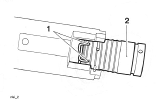
Note:
- Note the orientation of the hydraulic tensioner.
8. Evenly release the hydraulic tensioner mounting bolts until the plunger spring tension has been released.
9. Remove the hydraulic tensioner and discard the O-ring and gasket.
Installation
1. Check that number 1 cylinder is still at top dead centre (TDC).
2. Ensure that the wedge fitted earlier is still holding the camshaft drive chain tensioner blade in contact with the camshaft drive chain. Check that the camshaft timing marks point inwards and are level with the joint face of the head.
3. For engines fitted with the spring loaded tensioner, continue from step 4 to step 8. Then continue from step 21.
For engines fitted with the hydraulic tensioner, continue from step 9.
Engines Fitted with the Spring Loaded Tensioner
4. Check that the camshaft drive chain tensioner O-ring is not worn or damaged. If worn or damaged, replace the O-ring.
5. Set the tensioner plunger onto the first tooth of the ratchet (i.e. minimum extension) by manually lifting the tensioner pawl.
Tensioner Plunger Set-up
6. Fit the tensioner, complete with a new O-ring if necessary, to the cylinder head (ratchet facing upwards) and tighten the new retaining bolts to 9 Nm.
7. Fit the sealing washer to the centre bolt. Using finger pressure only, push the ratchet section of the tensioner into firm contact with the tensioner blade.
Refit the spring and centre nut to the tensioner.
Tighten the centre nut to 7 Nm.
8. Remove the camshaft drive chain tensioner blade wedge, taking care not to move or damage the tensioner blade.
Engines Fitted with the Hydraulic Tensioner
9. To set the hydraulic tensioner onto the first tooth of the ratchet (i.e. minimum extension) carry out the following:
Note:
- If installing a new hydraulic tensioner, do not release the plunger before fitting.
- If installing the original hydraulic tensioner, the engine oil must be drained out of the tensioner to enable the plunger to be set onto the first tooth of the ratchet.
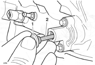
10. Hold the resister ring ends together and pull out the plunger.
- Resister ring ends
- Plunger
11. Remove the spring.
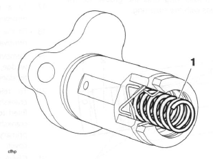
- Spring
12. While holding the resister ring in place, pour out the engine oil into a suitable container.
13. Ensure the resister ring is correctly located as shown in the illustration below.
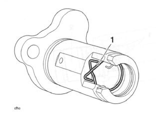
- Resister ring
14. Refit the spring.
15. Hold the resister ends together and push the plunger through the resister ring until the groove for the snap ring aligns with the snap ring.
- Resister ring
- Plunger
- Groove for snap ring
- Snap ring
16. When the groove aligns with the snap ring, release the resister ring and move one end of the snap ring into the groove. Slowly release the plunger to ensure that it is held in place.
- Groove for snap ring
- Snap ring
17. Fit a new O-ring and gasket to the hydraulic tensioner.
18. Fit the tensioner to the cylinder head as noted for removal. Tighten the bolts to 9 Nm.
19. Remove the camshaft drive chain tensioner blade wedge, taking care not to move or damage the tensioner blade.
20. To release the hydraulic tensioner, rotate the crankshaft 1/4 of a turn anti-clockwise using the bolt fitted to the end of the crankshaft. Then rotate the crankshaft clockwise until the 'dot' mark on the primary gear aligns with the line at the bottom of the cover.
21. Check that there is tension in the camshaft drive chain and the timing marks at the camshaft sprockets are correctly aligned.
Note:
- After fitting to the engine, the hydraulic tensioner will be empty of engine oil. After starting the engine, the camshaft drive chain and tensioner blade will be noisey until full pressure is felt at the tensioner plunger. This could take up to 5 seconds.
All Engines
22. Check that the tensioner plunger is correctly located in the middle of the camshaft drive chain tensioner blade when viewed from above.
23. Rotate the engine through 4 full revolutions, and reset number 1 cylinder to TDC. Ensure that the 'dot' mark on the primary gear aligns with the line at the bottom of the cover.
- 'Dot' mark
- Marker line
24. Check that the camshaft timing marks align as illustrated below.
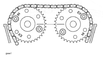
Camshaft to Cylinder Head Alignment Marks
25. Re-check the tensioner plunger location against the camshaft drive chain tensioner blade.
26. Refit the camshaft cover.
27. Fit a new gasket to the right hand crank cover.
28. Noting the position of the bolt fitted with the copper washer, refit the crank cover, tightening the fixings to 9 Nm.
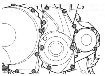
- Right hand crank cover
- Copper washer position
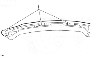
Camshaft Drive Chain Tensioner Blade - Daytona 675 - from VIN 381275
Disassembly
Note:
- For the purpose of this instruction, the top of the tensioner blade is where the pad is located.
1. Release the clips and remove the pad.
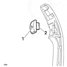
- Pad
- Clip (one side shown)
2. Detach the top hook from the tensioner blade.
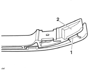
- Top hook
- Tensioner blade
3. Release the three side locating devices.
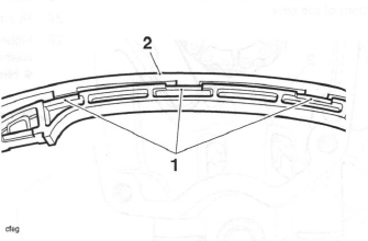
- Locating devices
- Facing blade
4. Release the three hooks and remove the facing blade.
- Hooks
Assembly
1. Assembly is the reverse of disassembly.
See also:
 Triumph Street Triple S - Service manual > Cylinder Head Description
The engine is fitted with an aluminium alloy cylinder head, which carries the camshafts, valves and spark plugs. The cylinder head is cast as a single entity and various components are permanently added after machining.
Triumph Street Triple S - Service manual > Camshafts
Removal 1. Remove the camshaft drive chain tensioner. Note: It is not necessary to remove the camshaft drive chain completely. Each camshaft and sprocket is removed as an assembly. Before commencing work, ensure the crankshaft 'dot' mark is in alignment with the line in the crankcase.
 Benelli Imperiale 400
 BMW F900XR
 Honda CB500X
 KTM 390 Adventure
 Triumph Street Triple S
 Yamaha MT-03
 Kawasaki Z400
 Triumph Street Triple S
 Yamaha MT-03