 Triumph Street Triple S - Service manual > Clutch
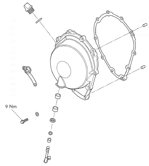
Exploded View - Clutch Cover
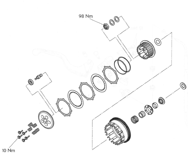
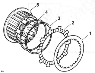
Exploded View - Clutch Assembly
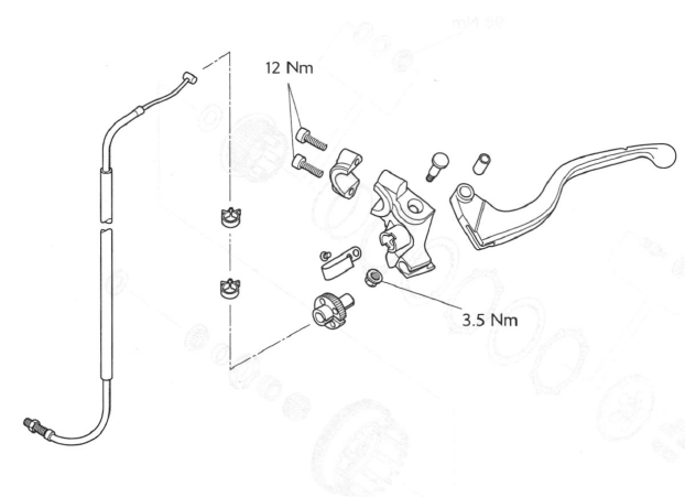
Exploded View - Clutch Controls
Clutch Cable
Removal
1. Remove the rider's seat.
2. Disconnect the battery, negative (black) lead first.
3. Slacken the cable locknut and release the adjuster at the clutch cover end to give maximum play in the cable.
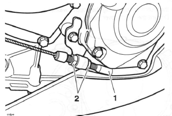
- Clutch cable
- Adjuster
4. Release the clutch cable from the actuating arm by pushing the inner cable nipple through the arm and sliding the cable out of the slot. Detach the cable from the bracket.
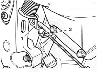
- Actuating arm
- Inner cable nipple
5. Align the cable adjuster and lever bracket slots.
6. Pull in the clutch lever and turn the inner cable, anticlockwise through the slots in the adjuster and locknut, until the cable can be detached from the lever by pushing downwards.
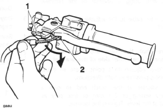
- Cable adjuster/lever bracket slots
- Cable release point
7. Remove the cable from the motorcycle noting the cable routing.
Inspection
1. Check the inner cable for free movement through the outer cable.
2. Examine the inner cable for frayed strands.
3. Examine the two inner cable nipples for signs of looseness and damage. Replace the cable if necessary.
Assembly
1. Position the cable to the motorcycle using the same routing as noted during removal.
2. Attach the inner cable to the clutch lever and actuating arm using a reversal of the removal process.
3. Refit the outer cable to the adjuster bracket at the clutch end.
Note:
- Ensure that the two adjuster nuts are positioned one either side of the bracket.
4. Set the lever adjuster to a point where an equal adjustment is possible in both directions.
5. Set the adjuster at the clutch end to give a preliminary setting of 2-3 mm of free play as measured at the lever. Tighten the locknut.
6. Operate the clutch lever several times and recheck the amount of free-play present.
7. Set the final adjustment of the cable to give 2-3 mm of free-play at the lever by turning the adjuster nut and locknut at the lever end.
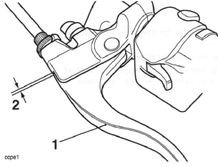
- Clutch lever
- Correct setting, 2-3 mm
8. Reconnect the battery, positive (red) lead first.
9. Refit the rider's seat.
Clutch
Disassembly
1. Remove the rider's seat.
2. Disconnect the battery, negative (black) lead first.
3. Daytona 675 only: Remove the lower fairings.
4. Release the clutch cable from the actuating arm.
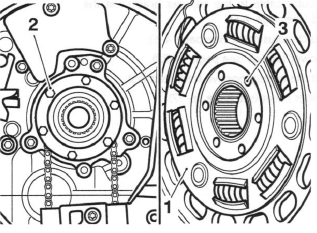
5. Remove the clutch cover, noting the copper washer position. Discard the clutch cover gasket.
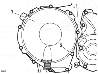
- Clutch cover
- Copper washer position
6. Undo the bolts and remove the springs and clutch pressure plate.
7. Remove the clutch pull-rod.
- Clutch pull-rod
- Clutch pressure plate
8. Remove the clutch friction plates and steel plates together with the anti-judder spring and anti-judder seat washer.
Note:
- Record the orientation of all components as they are removed. The plates must be assembled in the same order.
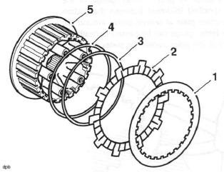
- Steel plate
- Inner fiction plate
- Anti-judder spring
- Anti-judder seat washer
- Clutch inner drum
Note:
- The inner and outermost friction plates are different to the remainder and are also different to each other. They must be fitted in their noted positions.
- The two outer steel plates are different to the other plates. They must be fitted in their noted positions.
- Store all plates in their correct fitted order to avoid confusion on installation.
- Refer to the following page of this section for details of clutch friction plate checking.
- It is not normally necessary to disassemble the clutch further, but if the clutch inner and outer drums are to be removed, proceed as follows:
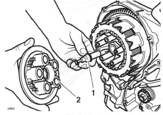
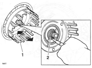
9. Insert service tool T3880026 into the splines of the clutch inner drum. Using finger pressure only, tighten the adjuster screw to allow the tool to grip the splines. Do not overtighten the adjuster screw.
- Service Tool T3880026
- Adjuster screw
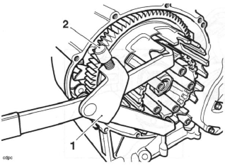
10. Retain the service tool to prevent the clutch inner drum from turning, then release the centre nut.
Remove the tool.
11. Remove the centre nut, Belleville washer, flat washer, clutch inner drum and thrust washer.
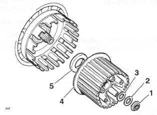
- Centre nut
- Belleville washer
- Flat washer
- Inner drum
- Thrust washer
12. Slide the clutch outer drum assembly gently backwards and forwards to dislodge the inner bearing sleeve. Carefully remove the bearing sleeve while supporting the clutch drum.
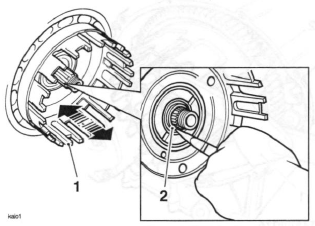
- Outer drum
- Bearing sleeve
13. Remove the clutch outer drum leaving the oil pump drive sprocket, bearing and sleeve in place on the input shaft.
Friction Plate Inspection
Thickness
1. If any friction plate thickness is outside the service limit, replace the friction plates as a set.
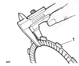
- Clutch friction plate
Friction plate thickness - all plates
Standard: 3.00 mm
Service limit: 2.80 mm
Bend/warp
Check all plates for bend and warp as follows:
1. Place the plate being checked on a clean surface plate and attempt to pass a feeler gauge of the maximum specified thickness between the friction plate and surface plate at several points around the plate. If the feeler gauge can be passed beneath the friction plate at any point, renew the plates as a set.
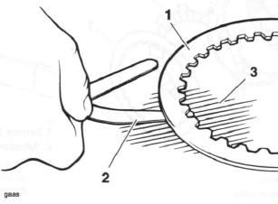
- Friction plate
- Feeler gauge
- Surface plate
Friction plate bend/warp
Standard: up to 0.15 mm
Service limit: 0.20 mm
Assembly
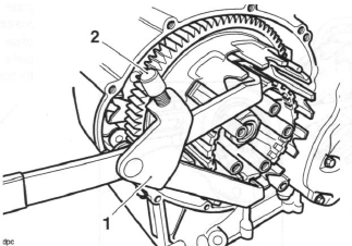
1. To fully engage the outer drum, insert a suitable tool to preload and align the primary gear and backlash eliminator gear through the hole shown in the illustration below.
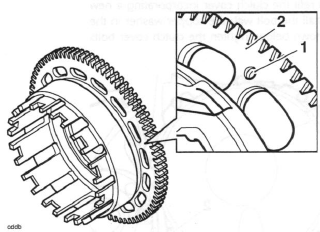
- Alignment hole
- Outer drum
2. Position the clutch outer drum assembly to the input shaft and align the oil pump drive pegs with the corresponding holes in the rear of the clutch outer drum.
- Clutch outer drum
- Oil pump sprocket drive pegs
- Oil pump drive holes
3. While holding the clutch outer drum in position and ensuring correct engagement with the oil pump drive, refit the bearing sleeve and bearing.
- Outer drum
- Bearing sleeve
Note:
- When the bearing sleeve is correctly fitted, it will be a flush fit with the clutch drum face.
4. Fit the thrust washer to the shaft.
5. Fit the clutch inner drum.
6. Fit the flat washer, a new Belleville washer ('OUT' mark facing outwards), and refit the centre nut.
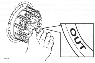
Belleville Washer 'OUT' Mark
7. Using service tool T3880026, prevent the clutch inner drum from turning, and tighten the clutch centre nut to 98 Nm. Remove the service tool.
- Service tool T3880026
8. Coat all clutch friction plates in clean engine oil before fitting the friction plates, steel plates, anti-judder spring and anti-judder seat washer to the clutch basket in the same order and orientation as noted during removal.
Note:
- The inner and outermost friction plates are different to the remainder and are also different to each other. They must be fitted in their noted positions.
- The two outer steel plates are different to the other plates. They must be fitted in their noted positions.
- Steel plate
- Inner fiction plate
- Anti-judder spring
- Anti-judder seat washer
- Clutch inner drum
9. Refit the clutch pull-rod.
10. Refit the clutch pressure plate together with the springs and bolts. Tighten the bolts to 10 Nm.
Note:
- The pull-rod should be free to move in and out and also it should be free to turn.
11. Clean and refit the clutch cover incorporating a new gasket. Install the bolt with the copper washer in the position shown below. Tighten the clutch cover bolts to 9 Nm.

- Clutch cover
- Copper washer position
12. Refit the outer cable to the adjuster bracket at the clutch end.
13. Set the clutch adjustment.
14. Refit the lower fairings.
15. Reconnect the battery positive (red) lead first.
16. Refit the rider's seat.
See also:
 Triumph Street Triple S - Service manual > Camshafts
Removal 1. Remove the camshaft drive chain tensioner. Note: It is not necessary to remove the camshaft drive chain completely. Each camshaft and sprocket is removed as an assembly. Before commencing work, ensure the crankshaft 'dot' mark is in alignment with the line in the crankcase.
Triumph Street Triple S - Service manual > Crankshaft, Connecting Rods and Pistons
Exploded View - Crankshaft, Connecting Rod, Piston and Liner
 Benelli Imperiale 400
 BMW F900XR
 Honda CB500X
 KTM 390 Adventure
 Triumph Street Triple S
 Yamaha MT-03
 Kawasaki Z400
 Triumph Street Triple S
 Yamaha MT-03