 Kawasaki Z400 - Service manual > Brakes
Brake System Inspection
Brake Fluid Leak (Brake Hose and Pipe) Inspection
- For ABS equipped models, remove the air cleaner housing (see Air Cleaner Housing Removal in the Fuel System (DFI) chapter).
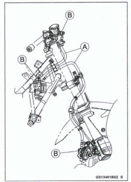
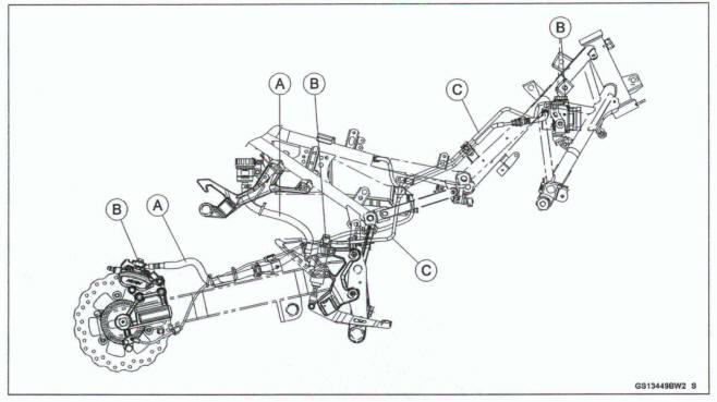
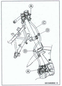
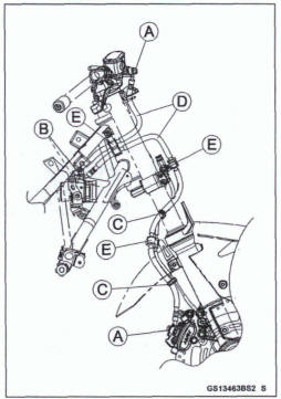
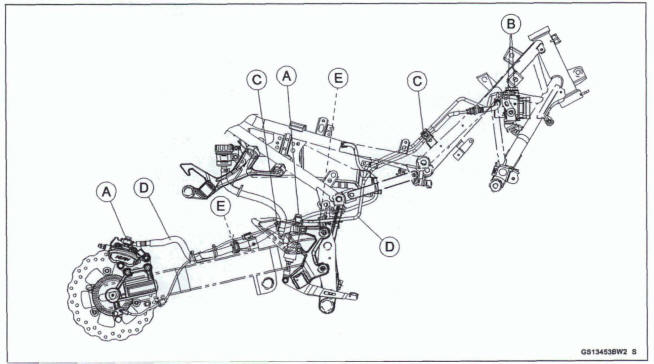
- Apply the brake lever or pedal and inspect the brake fluid leak from the brake hoses [A], fittings [B] and pipes [C] (ABS equipped models).
If the brake fluid leaked from any position, inspect or replace the problem part.
Brake Hose and Pipe Damage and Installation Condition Inspection
- For ABS equipped models, remove the air cleaner housing (see Air Cleaner Housing Removal in the Fuel System (DFI) chapter).
- Inspect the brake hoses, pipes (ABS equipped models) and fittings for deterioration, cracks and signs of leakage.
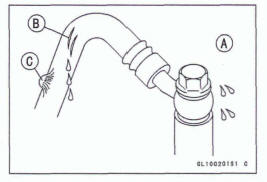
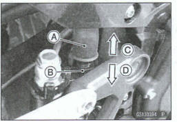
- The high pressure inside the brake line can cause fluid to leak [A] or the hose, pipe (ABS equipped models) to burst if the line is not properly maintained. Bend and twist the rubber hose while examining it.
Replace the hose and pipe (ABS equipped models) if any crack [B], bulge [C] or leakage is noticed.
Tighten any brake hose banjo bolts.
Torque -Brake Hem Banjo Bolts: 25 Nm (2.5 k*m, 18 ft*lb)
Brake Hose Banjo Bolts (ABS Hydraulic Unit): 33 N*m (3.4 kgf-m, 24 ft*lb)
- Inspect the bake hose and pipe routing.
If any brake hose and pipe (ABS equipped models) routing is incorrect, run the brake hose and pipe according to Cable, Wire, and Hose Routing section in the Appendix chapter.
Brake Operation Inspection
- Inspect the operation of the front and rear brake by running the vehicle on the dry road.
If the brake operation is insufficiency, inspect the brake system.
WARNING
When test riding the vehicle, be aware of surrounding traffic for your safety.
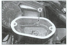
Brake Fluid Level Inspection
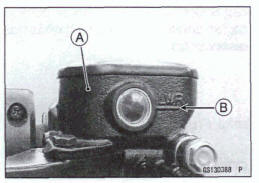
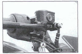
Check that the brake fluid level in the front brake fluid reservoir [A] is above the lower level line [B].
NOTE
Hold the reservoir horizontal turning the handlebar when checking brake fluid level.
If the fluid level is lower than the lower level line, fill the reservoir to the upper level line [A] in the reservoir.
- Tighten:
Torque - Front Brake Reservoir Cap Screws: 1.5 N-m (0.15 kgf*m, 13 in*lb)
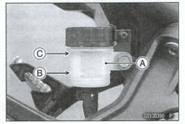
- Check that the brake fluid level in the rear brake fluid reservoir [A] is above the lower level line [B].
If the fluid level is lower than the lower level line, fill the reservoir to the upper level line [C].
WARNING
Mixing brands and types of brake fluid can reduce the brake system's effectiveness and cause an accident resulting in injury or death. Do not mix two brands of brake fluid. Change the brake fluid in the brake line completely if the brake fluid must be refilled but the type and brand of the brake fluid that is already in the reservoir are unidentified.
Recommended Disc Brake Fluid
Grade:
Front - DOT3 or DOT 4
Rear- DOT4
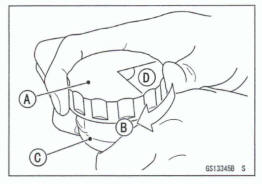
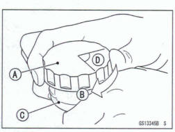
Follow the procedure below to install the rear brake fluid reservoir cap correctly.
- First, tighten the brake fluid reservoir cap [A] clockwise [B] by hand until slight resistance is felt indicating that the cap is seated on the reservoir body [C], then tighten the cap an additional 1/6 turn [D] while holding the brake fluid reservoir body.
Brake Fluid Change
NOTE
The procedure to change the front brake fluid is as follows.
Changing the rear brake fluid is the same as for the front brake.
- Level the brake fluid reservoir.
- Remove the reservoir cap and diaphragm.
- Remove the rubber cap [A] from the bleed valve on the caliper.
- Attach a clear plastic hose [B] to the bleed valve, and run the other end of the hose into a container.
- Fill the reservoir with fresh specified brake fluid.
- Change the brake fluid.
- Repeat this operation until fresh brake fluid comes out from the plastic hose or the color of the fluid changes.
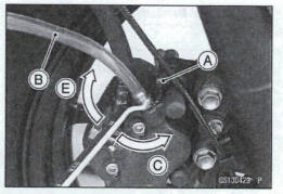
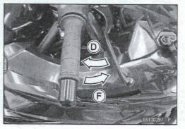
- Open the bleed valve [C].
- Apply the brake and hold it [D].
- Close the bleed valve [E].
- Release the brake [F].
NOTE
The fluid level must be checked often during the changing operation and replenished with fresh brake fluid. If the fluid in the reservoir runs out any time during the changing operation, the brakes will need to be bled since air will have entered the brake line.
- Remove the clear plastic hose.
- Install the diaphragm and reservoir cap.
- Tighten:
Torque - Front Brake Reservoir cap Screws: 1.5 N*m(0.15 kgf*m, 13 in*lb)
- Follow the procedure below to install the rear brake fluid reservoir cap correctly.
- First, tighten the rear brake fluid reservoir cap [A] clockwise [B] by hand until slight resistance is felt indicating that the cap is seated on the reservoir body [C], then tighten the cap an additional 116 turn [D] while holding the brake fluid reservoir body.
- Tighten the bleed valve, and install the rubber cap.
Torque - Bleed Valve: 5.4 Nm (0.55 kgf*m, 48 In*lb)
- After changing the fluid, check the brake for good braking power, no brake drag, and no fluid leakage.
If necessary, bleed the air from the lines.
Brake Hose and Pipe Replacement
NOTICE
Brake fluid quickly damages painted plastic surfaces; any spilled fluid should be completely washed away immediately.
- Remove
- Mud Guard (see Mud Guard Removal in the Frame chapter) Brake Hose Banjo Bolts [A] Clamp [B]
- Clear the brake hoses [C] from the brackets [D], and remove the brake hoses
When installing the brake hoses, note the following.
- Avoid sharp bending, kinking, flatting or twisting, and run the hoses according to Cable, Wire, and Hose Routing section in the Appendix chapter.
- There are washers on each side of the brake hose
fitting.
Replace them with new ones
- Tighten
Torque- Brake Hose Banjo Bolts: 25 N*m (2.5 kgf*m, 18 ft*lb)
- Fill the brake line after installing the brake hose (see Brake Fluid Change).
For ABS equipped models; note the following.
Remove:
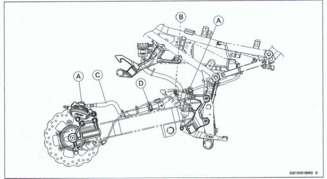
Air Cleaner Housing Bracket Frame Cover (see Frame Cover Removal in the Frame chapter) Mud Guard (see Mud Guard Removal in the Frame chapter) Brake Hose Banjo Bolts [A] Brake Hose Banjo Bolts (ABS Hydraulic Unit) [B] Clamps [C]
- Clear the brake hoses [D] from the brackets [E], and re move the brake hoses.
- There are washers on each side of the brake hose and pipe fitting. Replace them with new ones when installing.
- Install the brake pipes and brake hoses to the specified angle (see Cable, Wire, and Hose Routing section In the Appendix chapter).
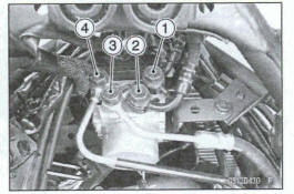
- Tighten the brake hose banjo bolts (ABS hydraulic unit) following- the specified tightening sequence [1- 41]
Torque - Brake Hose Banjo Bolts (ABS Hydraulic Unit): 33 N*m (3.4 kgf*m, 24 ft*lb)
- Tighten:
Torque - Brake Hose Banjo Bolts: 25 N*m (2.5 kgf-m, 18 ft-lb)
- Fill the brake line after installing the brake hose and pipe (see Brake Fluid Change).
Master Cylinder Rubber Parts Replacement
Front Master Cylinder Disassembly
- Remove the front master cylinder (see Front Master Cylinder Removal in the Brakes chapter).
- Remove:
Front Brake Reservoir Cap Screws [A] Reservoir Cap [B] Diaphragm Plate [C] Diaphragm [D]
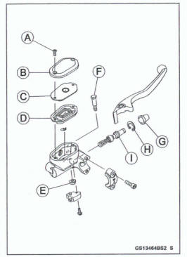
- Unscrew the locknut [E] and pivot bolt [F], and remove the brake lever.
- Remove the dust cover [G] and circlip [H]
Special Tool- Inside Circlip Pliers: 57001-143
- Pull out the piston assembly [I].
NOTICE
Do not remove the secondary cup from the piston since removal will damage it.
Replace
Diaphragm [D] Dust Cover [G] Circlip [H] Piston Assembly [I]
Rear Master Cylinder Disassembly
- Remove:
Rear Master Cylinder (see Rear Master Cylinder Removal in the Brakes chapter).
- Remove the circlip [A], connector [B] and O-ring [C].
Special Tool - Inside Circlip Pliers: 57001-143
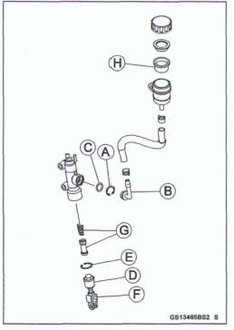
- Slide the dust cover [D] out of place, and remove the circlip [E].
- Pull out the push rod assembly [F].
- Remove the piston assembly [G].
NOTICE
Do not remove the secondary cup from the piston since removal will damage It.
- Replace:
Circlip [A] O-ring [C] Circlip [E] Push Rod Assembly [F] Piston Assembly [G] Diaphragm [H]
Master Cylinder Assembly
- Before assembly, clean all parts including the master cylinder with brake fluid or alcohol.
NOTICE
Except for the disc pads and disc, use only disc brake fluid, isopropyl alcohol, or ethyl alcohol for cleaning brake parts. Do not use any other fluid for cleaning these parts. Gasoline, engine oil, or any other petroleum distillate will cause deterioration of the rubber parts. Oil spilled on any part will be difficult to wash off completely, and will eventually deteriorate the rubber used in the disc brake.
- Apply brake fluid to the new parts and to the inner wall of the cylinder.
- Take care not to scratch the piston or the inner wall of the cylinder.
- Apply silicone grease to the followings.
Front: Brake Lever Pivot Bolt
Rear: Dust Cover of Push Rod Assembly
For the front master cylinder, tighten the brake lever pivot bolt and the locknut.
Torque -Brake Lever Pivot Bolt: 5.9 N*m (0.60 kgf-m, 52 In*lb) Brake Lever Pivot Bolt Locknut: 5.9 N-m (0.60 kgf*m, 52 in-lb)
Caliper Rubber Parts Replacement
Caliper Disassembly
- Remove
Caliper (see Front/Rear Caliper Removal in the Brakes chapter) Brake Pad (see Brake Pad Removal in the Brakes chapter)
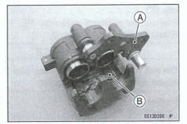
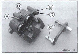
- Remove:
Caliper Holder [A] Pad Spring [B]
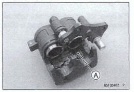
- Using compressed air, remove the pistons
- Cover the piston area with a clean, thick doth [A].
- Blow compressed air into the hole for the banjo bolt to remove the piston.
Warning
The piston in the brake caliper can crush hands and fingers. Never place your hand or fingers in front of the piston.
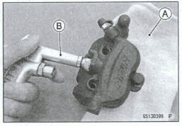
Pull out the piston by hand.
- When compressed air is not used, using the brake caliper piston pliers [A] remove the pistons [B].
Special Tool- Brake Caliper Piston Pliers
( 16
~
16
~
 26)
57001-1861
26)
57001-1861
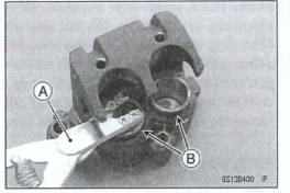
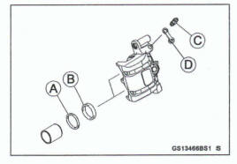
- Remove the dust seals [A] and fluid seals [B].
- Remove the bleed valve [C] and rubber cap [D]
Caliper Assembly
- Clean the caliper parts except for the pads.
NOTICE
For cleaning the parts, use only disc brake fluid, isopropyl alcohol, or ethyl alcohol.
- Install the bleed valve and rubber cap.
Torque - Bleed Valve: 5.4 N*m (0.55 kgf-m, 48 in-lb)
- Replace the fluid seals [A] with new ones.
- Apply silicone grease to the fluid seals, and install them into the cylinders by hand.
- Replace the dust seals [B] with new ones if they are damaged.
- Apply silicone grease to the dust seals and install them into the cylinders by hand.
- Apply brake fluid to the outside of the pistons, and push them into each cylinder by hand.
- Check the shaft rubber friction boot [A] and the dust cover [B] replace them with new ones if they are damaged.
- Apply a silicone grease to the caliper holder shafts [C] and holes [D] .
- Install the pad spring [A] in the caliper as shown.
- Install the removed parts (see appropriate chapters)
- Wipe up any spilled brake fluid on the caliper with wet cloth.
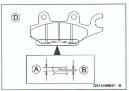
Brake Pad Wear Inspection
- Remove the brake pads (see Front/Rear Brake Pad Removal in the Brakes chapter).
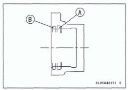
- Check the lining thickness [A] of the pads in each caliper.
If the lining thickness of either pad is less than the service limit [B], replace both pads in the caliper as a set.
Front Brake Pad [C]
Rear Brake Pad [D]
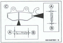
Pad Lining Thickness
Standard:
Front 4.5 mm (0.18 in.)
Rear 4.5 mm (0.18 in.)
Service Limit:
Front 1.0 mm (0.04 in.)
Rear I .5 mm (0.06 in.)
Brake Light Switch Operation Inspection
- Turn the ignition switch on.
- The brake light [A] should go on when the brake lever is applied or after the brake pedal is depressed about 10 mm (0.39 in.).
If it does not, adjust the brake light switch.
- Remove the right front footpeg bracket bolts [A].
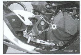
- While holding the switch body, turn the adjusting nut to adjust the switch
Switch Body [A]
Adjusting Nut [B]
Light sooner as the body rises [C]
Light later as the body lowers [D]
NOTICE
To avoid damaging the electrical connections inside the switch, be sure that the switch body does not turn during adjustment.
- Tighten:
Torque - Front Footpeg Bracket Bolts: 25 N*m (2.5 kgf*m, 18 ft*lb)
If it does not go on, inspect or replace the following parts.
Battery (see Charging Condition Inspection in the Electrical System chapter) Brake Light (LED) (see Brake/Tail Light Removal/Installation in the Electrical System chapter) Turn Signal Relay Fuse 10 A (see Fuse Inspection in the Electrical System chapter) Front Brake Light Switch [A] (see Switch Inspection in the Electrical System chapter) Rear Brake Light Switch (see Switch Inspection in the Electrical System chapter) Harness (see Wiring Inspection in the Electrical System chapter)
See also:
 Kawasaki Z400 - Service manual > Final Drive
Drive Chain Lubrication Condition Inspection Lubrication is necessary after riding through rain or on wet roads, or any time that the chain appears dry. Use a lubricant for sealed chains to prevent deterioration of chain seals. If the chain is especially dirty, clean it using a cleaner for sealed chains following the instructions supplied by the chain cleaner manufacturer.
Kawasaki Z400 - Service manual > Suspension
Suspension System Inspection Front Fork/Rear Shock Absorber Operation Inspection Pump the forks dam and up [A] 4 or 5 times, and inspect the smooth stroke.
 Benelli Imperiale 400
 BMW F900XR
 Honda CB500X
 KTM 390 Adventure
 Triumph Street Triple S
 Yamaha MT-03
 Kawasaki Z400
 Triumph Street Triple S
 Yamaha MT-03