 Kawasaki Z400 - Service manual > Brake Disc
Brake Disc Removal
- Remove the wheels (see Front/Rear Wheel Removal in the Wheels/tires chapter).
- Remove the brake disc mounting bolts [A] and brake disc [B].
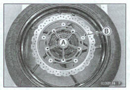
NOTE
Handle the wheel rotation sensor rotor carefully and do not apply the external force to deform it. Them is a possibility that the sensor cannot read the signal correctly from the rotor.
Brake Disc Instaltation
- Install the brake disc on the wheel so that the marked side [A] faces out.
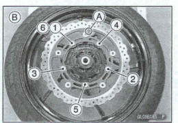
- Apply a non-permanent locking agent to the threads of the front and rear brake disc mounting bolts.
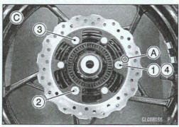
- Tighten the front and rear brake dim mounting bolts following
the specified tightening sequence.
Front Brake Disc [B] Rear Brake Disc [C]
Torque - Brake DISC Mounting Bob. 27 N*m (2.8 kgf-m, 20 ft*lb)
NOTE
Handle the wheel rotation sensor rotor carefully and do not apply the external force to deform it. There is a possibility that the sensor cannot read the signal correctly from m rotor.
Brake Disc Wear Inspection
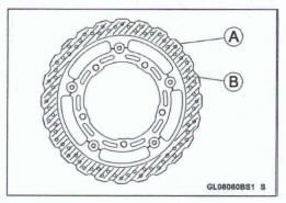
- Measure the thickness of each disc [A] at the point where it has worn the most.
*If the disc has worn past the service limit, replace it.
Measuring Area [B]
Brake Discs Thickness
Standard:
Front 4.3 - 4.7 mm (0.17 - 0.19 in.)
Rear 4.8 - 5.2 mm (0.19 - 0.20 In.)
Service Limit:
Front 4.0 mm (0.16 in.)
Rear 4.5 mm (0.18 In.)
Brake Disc Warp Inspection
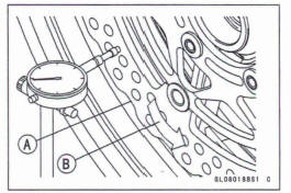
- Raise the front/rear wheel off the ground.
For front disc inspection, turn the handlebar fully to one side.
Set up a dial gauge against the disc [A] as shown and measure disc runout, while turning [B] the wheel by hand.
*If runout exceeds the service limit, replace the disc.
Disc Runout Standard: Service Limit: TIR 0.15 mm (0.0059 In.) or less TIR 0.3 mm (0.013 In.)
Brake Fluid
Brake Fluid Level Inspection
- Refer to the Brake Fluid Level Inspection in the Periodic Maintenance chapter
Brake Fluid Change
- Refer to the Brake Fluid Change in the Periodic Maintenance chapter.
Brake Line Bleeding
The brake fluid has a very low compression coefficient so that almost all the movement of the brake lever or pedal is transmitted directly to the caliper for braking action. Air, however, is easily compressed. When air enters the brake lines, brake lever or pedal movement will be partially used in compressing the air. This will make the lever or pedal feel spongy, and there will be a loss in braking power
WARNING
Air in the brake lines diminish braking performance and can cause an accident resulting in injury or death. If the brake lever or pedal has a soft or "spongy" feeling mushy when it is applied, there might be air In the brake lines or the brake may be defective. Do not operate the vehicle and service the brake system Immediately.
NOTICE
Brake fluid quickly damage painted plastic surfaces; any spilled fluid should be completely washed away immediately.
NOTE
The procedure to bleed the front brake line is as follows.
Bleeding the rear brake line is the same as for the front brake.
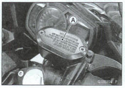
- Remove the reservoir cap [A], diaphragm plate and diaphragm.
- Fill the reservoir with fresh brake fluid to the upper level line in the reservoir.
Brake Fluid Grade
Front: DOT3 or DOT4
Rear: DOT4
- Slowly pump the brake lever several times until no air bubbles can be seen rising up through the fluid from the holes at the bottom of the reservoir.
Bleed the air completely from the master cylinder by this operation.
- Remove the rubber cap from the bleed valve [A] on the caliper.
- Attach a clear plastic hose [B] to the bleed valve, and run the other end of the hose into a container
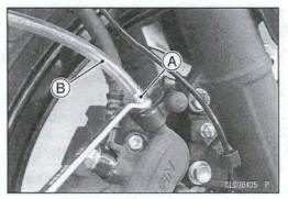
- Bleed the brake line and the caliper.
Repeat this operation until no more air can be seen coming out into the plastic hose.
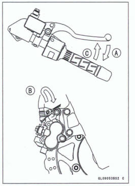
- Pump the brake lever until it becomes hard, and apply the brake and hold it [A].
- Quickly open and close [B] the bleed valve while holding the brake applied.
- Release the brake [C].
NOTICE
After pumping the brake lever several times, releasing It without opening and closing of the bleed valve may cause brake fluid to be blown back from the master cylinder reservoir. Brake fluid spilt on painted surfaces and plastic parts will quickly damage them. Be sure to open and close the bleed valve.
NOTE
- The fluid level must be checked often during the bleeding operation and replenished with fresh brake fluid as m-. If the fluid in the reservoir- runs completely out any time during bleeding, the bleeding operation must be done aver again 1Zwn the beginning since air will have entered the line.
- Tap the brake hose lightly from the caliper to the reservoir for more complete bleeding.
Remove the dear plastic hose.
Install the diaphragm, diaphragm plate and reservoir cap.
Tighten:
Torque - Front Brake Reservoir Cap Screws: 1.5 Nm (0.15 kg*fm, 13 In-lb)
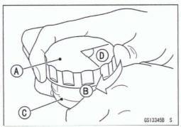
Follow the procedure below to install the rear brake fluid reservoir cap correctly.
First, tighten the rear Me fluid reservoir cap [A] clockwise [B] by hand until slight resistance is felt indicating that the cap is seated on the reservoir body [C], then tighten the cap an additional 1/6 turn [D] while holding the brake fluid reservoir body.
- Tighten the bleed valve, and install the rubber cap.
Torque -Bled Valve: 5.4 N-m (0.55 kgf-m, 48 In-lb)
- Check the fluid level (see Brake Fluid Level Inspection in the Periodic Maintenance chapter).
- After bleeding is done, check the brake for good braking power, no brake drag, and no fluid leakage.
WARNING
When working with the disc brake, observe the precautions listed below.
- Never reuse old brake fluid.
- Do not use fluid from a container that has been left
unsealed or that has been open for a long time.
Do not mix two types and brands of fluid for use in the brake. This lowers the brake fluid boiling point and could cause the brake to be ineffective.
It may also cause the rubber brake parts to deteriorate.
Do not leave the reservoir cap off for any length of time to avoid moisture contamination of the fluid.
- Do not change the fluid In the rain or when a strong wind k blowing.
- Except for the disc pads and disc, use only disc brake fluid, isopropyl alcohol, or ethyl alcohol for cleaning of the brake parts. Do not use any other fluid for cleaning these parts. Gasoline, engine oil, or any other petroleum distillate will cause deterioration of the rubber parts. Oil spilled on any part will be difficult to wash off completely and will eventually deteriorate the rubber used in the disc brake.
- When handling the disc pads or disc, be careful
that no disc brake fluid or any oil gets on them.
Clean Many fluid or oil that inadvertently gets on the pads or disc with a high flash-point solvent.
Do not use one which will leave an oily residue.
Replace the pads with new ones if they cannot be cleaned satisfactorily.
- Brake fluid quickly damages painted surfaces; any spilled fluid should be completely wiped up immediately.
- If any of the brake line fittings or the bleed valve is opened at any time, the AIR MUST BE BLED FROM THE BRAKE LINE.
Brake Hose
Brake Hose Removal/Installation
- Refer to the Brake Hose and Pipe Replacement in the Periodic Maintenance chapter
Brake Hose Inspection
- Refer to the Brake Hose and Pipe Damage and Installation Condition Inspection in the Periodic Maintenance chapter.
See also:
 Kawasaki Z400 - Service manual > Master Cylinder
Front Master Cylinder Removal Remove the banjo bolt [A] to disconnect the brake hose from the master cylinder (see Brake Hose Removal/Installation). Remove the damp bolts [B] and remove the master cylinder [C] with the reservoir, brake lever, and brake switch as an assembly. Disconnect the front brake light switch connector [D].
Kawasaki Z400 - Service manual > Anti-Lock Brake System (Equipped Models)
Parts Location Front Wheel Rotation Sensor [A] Front Wheel Rotation Sensor Rotor [B]
 Benelli Imperiale 400
 BMW F900XR
 Honda CB500X
 KTM 390 Adventure
 Triumph Street Triple S
 Yamaha MT-03
 Kawasaki Z400
 Triumph Street Triple S
 Yamaha MT-03