 Kawasaki Z400 - Service manual > Air Switching Valve
Air Switching Valve Operation Test
- Refer to the Air Suction System Damage Inspection in the Periodic Maintenance chapter
Air Switching Valve Unit Test
- Remove the air switching valve (see Air Switching Valve Removal in the Engine Top End chapter).
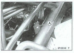
- Connect a digital meter [A] to the air witching valve terminals as shown.
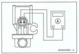
Air Switching Valve Resistance Standard: 20 - 24 0 m0.C (68ºF)
*If the digital meter does not read as specified value, replace it with a new one.
- Connect the 12 V battery [A] to the air switching valve terminals as shown.
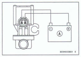
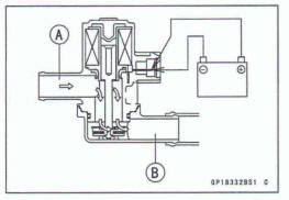
- Blow the air to the intake air dud [A], and make sure does not flow the blown air from the outlet air duct [B].
- Disconnect the 12 V battery.
- Blow the air to the intake air duct [A] again, and make sure flow the blown air from the outlet air duct [B].
*If the air switching valve does not operate as described, replace it with a new one.
NOTE
To check air flow through the air switching valve, just blow through the air switching valve hose (intake side).
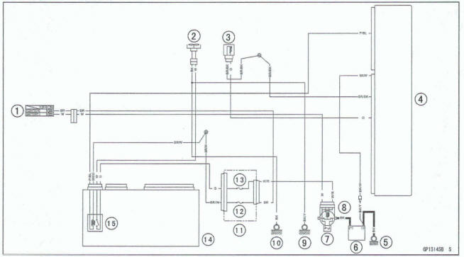
Air Switching Valve Circuit
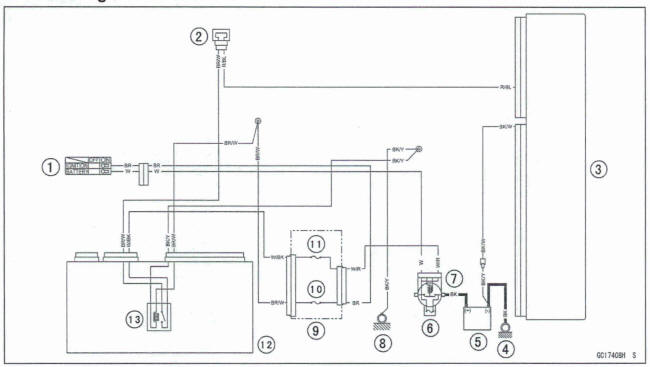
- Ignition Switch
- Air Switching Valve
- ECU
- Engine Ground
- Battery
- Main Fuse 30 A
- Starter Relay
- Frame Ground (2)
- Fuse Box (1)
- Ignition Fuse 10 A
- ECU Fuse 15 A
- Relay Box
- ECU Main Relay
Radiator Fan System
Fan Motor Inspection
- Remove the right middle fairing (see Middle Fairing Removal in the Frame chapter).
- Disconnect the connector [A].
- Using an auxiliary leads, supply battery power to the fan motor.
*If the fan does not rotate, the fan motor is defective and must be replaced.
Radiator Fan Circuit
- Ignition Switch
- Fan Motor
- Water Temperature Sensor
- ECU
- Engine Ground
- Battery
- Main Fuse 30 A
- Starter Relay
- Frame Ground (8)
- Frame Ground (1)
- Fuse Box (1)
- Ignition Fuse 10 A
- Fan Fuse 15 A
- Relay Box
- Radiator Fan Relay
See also:
 Kawasaki Z400 - Service manual > Lighting System
This motorcycle adopt the daylight system and have a headlight circuit relay in the relay box. The headlight does not go on when the ignition switch and the engine stop switch are first turned on. The headlight comes on after the starter button is released and stays on until the ignition switch is turned off. The headlight will go out momentarily whenever the starter button is pressed and come back on when the button is released.
Kawasaki Z400 - Service manual > Meter, Gauge, Indicator Unit
Meter Unit Removal Remove: Headlight (LED) Assembly (see Headlight (LED) Assembly Removal/Installation) Vehicle-down Sensor [A] (see Vehicle-down Sensor Removal in the Fuel System (DFI) chapter) Meter Mounting Screws [B] Pull up the meter unit [A]. Slide the dust cover [B], and disconnect the meter connector [C].
 Benelli Imperiale 400
 BMW F900XR
 Honda CB500X
 KTM 390 Adventure
 Triumph Street Triple S
 Yamaha MT-03
 Kawasaki Z400
 Triumph Street Triple S
 Yamaha MT-03