 Kawasaki Z400 - Service manual > Meter, Gauge, Indicator Unit
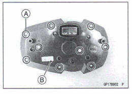
Meter Unit Removal
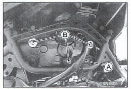
- Remove: Headlight (LED) Assembly (see Headlight (LED) Assembly Removal/Installation) Vehicle-down Sensor [A] (see Vehicle-down Sensor Removal in the Fuel System (DFI) chapter) Meter Mounting Screws [B]
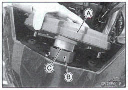
- Pull up the meter unit [A].
- Slide the dust cover [B], and disconnect the meter connector [C].
Meter Unit Installation
- Installation is the reverse of removal.
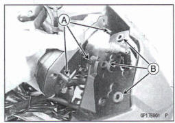
- Check that the grommets [A] are In place on the upper inner fairing [B].
- Insert the projections [A] in the grommets [B]
- Install the removed parts (see appropriate chapters).
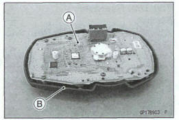
Meter Unit Disassembly/Assembly
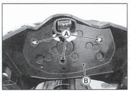
- Remove: Meter Unit (see Meter Unit Removal) Meter Assembly Screws [A] Lower Meter Cover [B]
- Separate the meter assembly [A] and upper meter cover [B].
- Assembly is the reverse of removal.
- Tighten:
Torque -Meter Assembly Screw: 1.2 N-m (0.12 kgf-m, 11 in-lb)
Meter Operation Inspection
Check 1: Meter Unit Switching Inspection Display Mode Setting
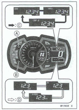
- Turn the ignition switch on and check the following.
- By pushing the upper meter button [A] or lower meter
button (B] each time, check that the display changes as
shown.
Pushing Upper Meter Button [C] Pushing Lower Meter Button [D]
*If the display function does not work, replace the meter assembly.
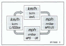
Unit Setting
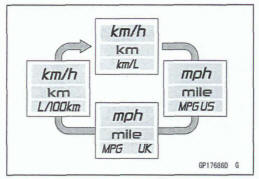
- Set the 000 mode by pushing the upper meter button.
- By pushing the lower meter button each time while the upper meter button pushed in, check that the display changes as shown.
NOTE
Mile/km display can alternate between English and metric modes (mile and km) in the digital meter. Make sum that km or mile acxod5ng to local regulations is correctly displayed before riding.
*If the display function does not work, replace the meter assembly.
Clock Setting
- Push the upper meter button [A] and lower meter button [B] and hold it.
The clock setting menu (hour and minute) should blink [C]
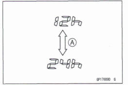
- Push the lower meter button and hold it.
"12h" or "24h" display is appeared.
- Push the upper meter button to select '12hn or "24hn [A].
- Push the lower meter button.
- The hour display [A] starts blinking.
- By pushing the upper meter button each time, check that the hour display changes
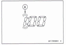
- By pushing the lower meter button, check that the hour display decides and minute display [A] starts blinking.
- By pushing the upper meter button each time, check that the minute display changes
- By pushing the lower meter button, check that the hour and minute display start blinking.
- By pushing the upper meter button, check that the hour and minute &splay decide.
- When both hour and minute display is blinking, by pushing the lower meter button, check that the hour display start blinking. This blinking returns the hour setting display.
*If the display function does not work, replace the meter assembly.
Meter System lnspection
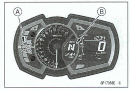
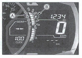
Check 2-1: Battery Warning lndicator Inspection
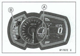
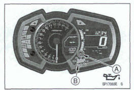
- When the battery condition is low voltage (1 0.8 - 11.2 V or less) or high voltage (1 5.5 - 16.5 V or more), the battery warning indiitor [A] and red warning indicator light (LED) [B] go on.
*If the battery warning indicator and red warning indicator light (LED) go on, inspect the charging voltage (see Charging Voltage Inspection).
*If the charging voltage is good, replace the meter assembly.
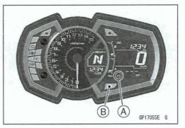
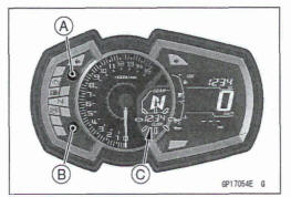
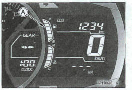
Check 2-2: Gear Position lndlcator lnspection
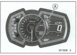
- Turn the ignition switch on and shii the transmission gear into neutral position.
OThe green neutral indicator light (LED) [A] goes on, and the gear position indicator is displayed the 'N" position [B].
- Set the low gear position, and check that the display changes to '1" mark [A] and the green neutral indicator light (LED) [B] goes off.
- Using the rear stand, raise the rear wheel off the ground.
- Rotate the rear wheel by hand and change the gear position.
- Check that the display corresponding to each gear position (1, N, 2,3,4,5 or 6) appears
*If the display function does not work, check the following parts.
Gear Position Sensor (see Gear Position Sensor Input Voltage Inspection in the Fuel System (DFI) chapter) Wiring (see Meter Unit Circuit) *If the above parts are good, replace the meter assembly and/or ECU
Meter Unit Inspection
- Remove the meter unit [A] (see Meter Unit Removal).
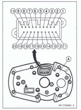
[1] Unused
[2] Unused
[3] Unused
[4] Unused
[5] Unused
[6] Red Warning Indicator Light (LED) (-) m Green Neutral Indicator Light (LED) (-)
[8] Yellow ABS Indicator Light (LED) (-) [Equipped Models]
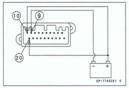
[9] Ground (-)
[l0] Ignition (+)
[11] Fuel Level Sensor
[12] Rear Wheel Rotation Sensor Pulse
[13] ECU Communication Line
[14] Unused
[15] Tachometer Pulse
[16] Green Right Turn Signal Indicator Light (LED) (+)
[17] Blue High Beam Indicator Light (LED) (+)
[18] Unused
[19] Green Left Turn Signal Indicator Light (LED) (+)
[20] Battery (+I
NOTICE
Do not drop the metter unit. Do not short each terminal.
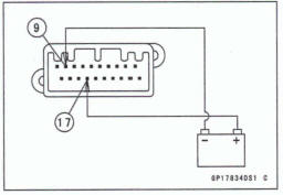
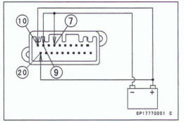
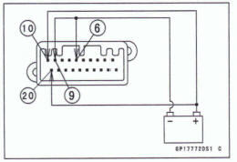
Check 3-1: Meter Unit Primary Operation Check
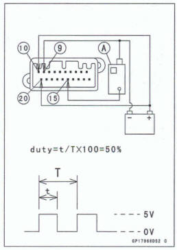
Using the auxiliary leads, conned the 12 V battery to the meter unit connector as follows.
- Connect the battery positive (+) terminal to the terminal [20].
- Conned the battery negative (-) terminal to the terminal [9].
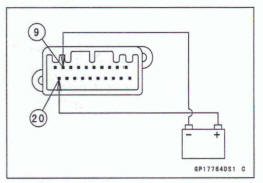
- Connect the terminal [lo] to the battery (+) terminal.
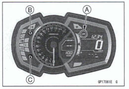
- Check the following items
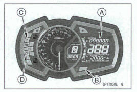
- The tachometer needle sweeps to the maximum reading, then sweep back to the minimum reading.
- The LCD display and meter illuminations should turn on.
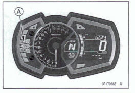
- All the LCD segments [A] appear for few seconds.
- The red warning indicator light (LED) [B] goes on for few seconds.
- Following indicator lights remain on.
Yellow Engine Warning Indicator Light (LED) [C] Yellow ABS Indicator Light (LED) [D](if equipped)
* If the meter unit does not work property, replace the meter assembly.
NOTE
This meter unit has a failure detection function of the coimmunic8tion. When the communication error was detected, the meter unit alerts the rider by the yellow engine warning indicator light (LED) goes on.
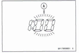
- Make sure that the fuel gauge segments [A] and indicator on the LCD start blinking approx. 5 seconds after turning on the meter unit.
*If the meter unit does not work properly, replace the meter assembly.
NOTE
This miter unit has a failure detection function (for open or short) of the fuel gauge. When the fuel gauge is open or short, the meter unit alerts the rider by the all fuel gauge segments blink in the display
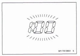
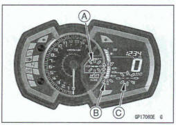
- Make sum that the following indicators on the LCD start
blinking approx. 10 seconds after turning on the meter
unit.
Gear Position Indicator with '-- Message [A] All Segments of Water Temperature Gauge [B] and Indicator Multifunction Display with '- -.-" Message [C]
NOTE
This meter unit has a failure detection function (for open or short) of the water temperature gauge. When the water temperature gauge is open or short, the meter unit alerts the rider by the all water temperature gauge segments blink in the display.
*If the meter unit does not work properly, replace the meter assembly.
Check 3-2: Meter Communication Line (Service Code 39) Check
- Connect the leads in the same circuit as Check 3-1.
- The yellow engine warning indicator light (LED) should , remains on.
- Set the OD0 mode [A] by pushing the upper meter button [B]
- Push the upper meter button and lower meter button [C] simultaneously for more than 2 seconds.
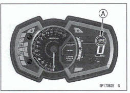
- Check the following items.
The number '39" [A] in the display appears.
- Push the upper meter button and lower meter button again for more than 2 seconds.
- Check the following items
The display returns OD0 mode from number '39."
*if the meter unit does not work properly, replace the meter assembly.
NOTE
- The number '39" is service code of Self-Diagnosis (see Fuel System (DFI) chapter). It is the service code of the meter communication line error.
- The number 39" in the display disappear when the meter unit is connected to main harness of the normal motorcycle.
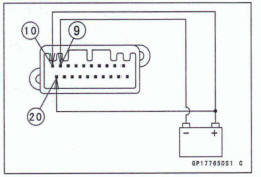
Check 3-3: Blue High Beam Indicator Light (LED) inspection
- Connect the terminal [17] to the battery (+) terminal.
- Connect the terminal [9] to the battery (-) terminal.
- Check that the blue high beam indicator light (LED) [A] goes on.
*If the indicator light (LED) does not go on, replace the meter assembly.
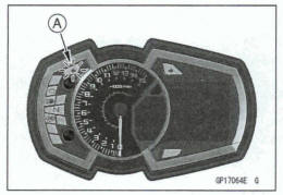
Check 34: Green Left Turn Signal Indicator Light (LED) Inspection
- Connect the terminal [I91 to the battery (+) terminal.
- Connect the terminal [9] to the battery (-) terminal.
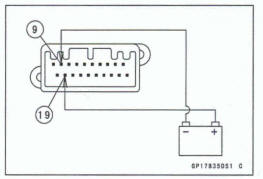
- Check that the green left turn signal indicator light (LED) [A] goes on.
*If the indicator light (LED) does not go on, replace the meter assembly.
Check 3-5: Green Right Turn Signal Indicator Light (LED) Inspection
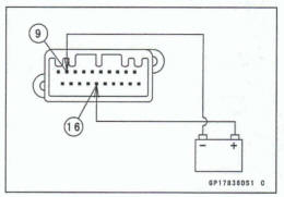
- Connect the terminal [16] to the battery (+) terminal.
- Connect the terminal [9] to the battery (-) terminal.
- Check that the green right turn signal indicator light (LED) [A1 goes on.
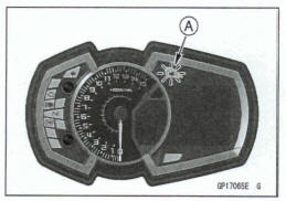
*If the indicator light (LED) does not go on, replace the meter assembly.
Check 36: Green Neutral Indicator Light (LED) inspection
- Connect the leads in the same circuit as Check 3-1.
- Connect the terminal [7] to the battery (-) terminal.
- Check that the green neutral indicator light (LED) [A] goes on.
*If the indicator light (LED) does not go on, replace the meter assembly.
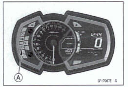
Check 3-7: Yellow ABS Indicator Light (LED) Inspection (Equipped Model)
- Connect the leads in the same circuit as Check 3-1.
The yellow ABS indicator light (LED) goes on.
- Connect the terminal [a] to the battery (-) terminal.
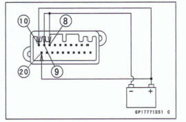
- Check that the yellow ABS indicator light (LED) [A] goes off.
*If the indicator light (LED) does not go off, replace the meter assembly.
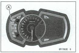
Check 3-8: Red Warning Indicator Light (LED) Inspection (Oil Pressure Warning)
- Connect the leads in the same circuit as Check 3-1.
- Connect the terminal [6] to the battery (-) terminal.
- Check that the oil pressure warning indicator [A] and red warning indicator light (LED) [B] goes on approx. 5 seconds later.
*If the oil pressure warning Indicator and indicator light (LED) dm not go on, replace the meter assembly
Check 3-9: Fuel Gauge Inspection
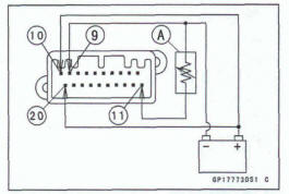
- Connect the leads in the same circuit as Check 3-1.
The all segments of the fuel gauge in the display will blink
- Connect the variable rheostat [A] to the terminal [11] and the battery (-) terminal.
- Check that the number of segments on the fuel gauge [A] matches the resistance value of the variable rheostat.
After changing the resistance between the terminal [11]
and ground, the segment (s) in the fuel gauge should
change after 15 seconds 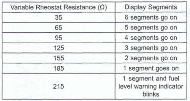
If the display function does not work properly, replace the meter assembly.
Check 3-1 0: Speedometer Check
- Connect the leads in the same circuit as Check 3-1.
- The speed equivalent to the input frequency is indicated in the oscillator [A], if the square wave is input into terminal [12].
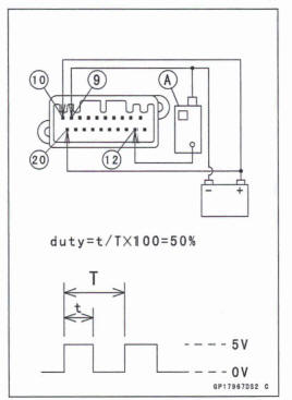
Indicates approximately 60 km/h if the input frequency is approximately 445 Hz.
Indicates approximately 60 mph if the input frequency is approximately 71 5 Hz.
*If the meter function does not work properly, replace the meter assembly.
NOTE
- The input frequency of the oscillator adds the integrated value of the odometer.
- The integrated value of the odometer cannot be reset.
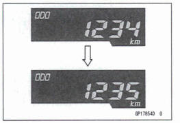
Check 3-11: Odometer Check
- Check the odometer with the speedometer check in the same way
*If value indicated in the odometer is not added, replace the meter assembly.
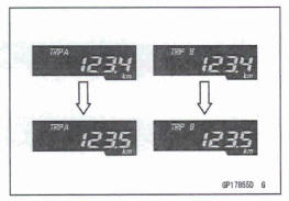
- Check that when the upper meter button is pushed for more than two seconds, the figure display turns to 0.0
*If the figure display does not indicate 0.0, replace the meter assembly.
NOTE
The data of the trip meters are maintained even if the battery is disconnected.
Check 3-1 3: Tachometer Check
- Connect the leads in the same circuit as Check 3-1.
- The engine speed (rpm) equivalent to the input frequency is indicated in the oscillator [A], if the square wave is input into terminal [15].
Indicates approximately 6 000 rpm if the input frequency is approximately 200 Hz.
*If the meter function does not work properly, replace the meter assembly.
Check 3-14: Other Inspection
The following items are displayed while running
AVERAGE
CURRENT
RANGE
ECO Mark
- When the above item is faulty indication check the following
items.
Wring (see Wiring Inspection) ECU Communication Line (see ECU Communication Line Inspection in the Fuel System (DFI) chapter) Fuel Injectors (see Fuel Injectors (Service Code 41,42) section in the Fuel System (DFI) chapter) Rear Wheel Rotation Sensor (see Rear Wheel Rotation Sensor (Service Code 24) section in the Fuel System (DFI) chapter) Crankshaft Sensor (see Crankshaft Sensor Inspection)
- When the coolant temperature gauge is faulty indication
check the following items.
Wring (see Wring Inspection) ECU Communication Line (see ECU Communication Line Inspection in the Fuel System (DFI) chapter) Water Temperature Sensor (see Water Temperature Sensor Inspection)
*If the above items are good, replace the meter assembly and/or ECU.
Fuel Level Sensor Line Self-Diagnosis Mode Inspection
NOTE
Usually when the open or short of the fuel level sensor circuit is detected, it becomes the Fuel Level Sensor Line Self-Diagnosis Mode.
- The all segments [A] of the fuel gauge and fuel level warning indicator [B] in the display will Mink. (This function is Fuel Level Sensor Line Self-Diagnosis Mode.)
*If the meter enters the self-diagnosis mode when the meter is installed in the motorcycle, check the fuel level sensor (see Fuel Level Sensor Inspection) and wiring.
*lf the fuel level sensor and wiring are good, replace the meter assembly.
Meter Circuit
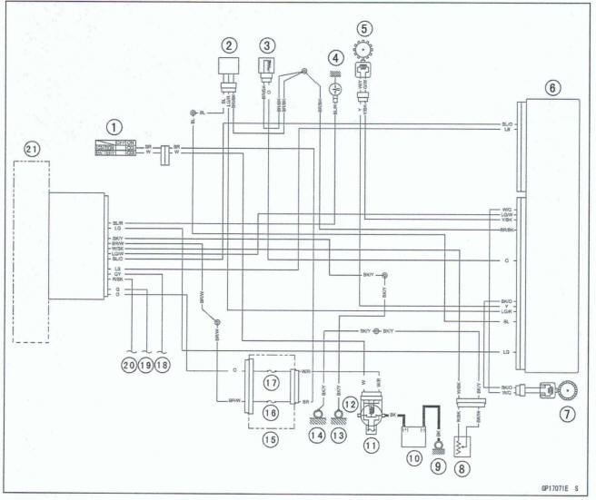
- Ignition Switch
- Gear Position Sensor
- Water Temperature Sensor
- Oil Pressure Switch
- Crankshaft Sensor
- ECU
- Rear Wheel Rotation Sensor
- Fuel Level Sensor
- Engine Ground
- Battery
- Main Fuse 30 A
- Starter Relay
- Frame Ground (4)
- Frame Ground (2)
- Fuse Box (1)
- Ignition Fuse 10 A
- Meter Fuse 10 A
- To Turn Signal Switch (Right)
- To Turn Signal Switch (Left)
- To Headlight Hi Beam
- Meter Unit
Meter Circuit (ABS Equipped Models)
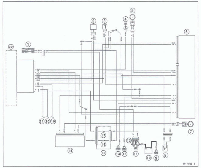
- Ignition Switch.
- Gear Position Sensor
- Water Temperature Sensor
- Oil Pressure Switch
- Crankshaft Sensor
- ECU
- Rear Wheel Rotation Sensor
- Fuel Level Sensor
- Engine Ground
- Battery
- Main Fuse 30 A
- Starter Relay
- Frame Ground (4)
- Frame Ground (2)
- Fuse Box (1)
- Ignition Fuse 10 A
- Meter Fuse 10 A
- ABS Hydraulic Unit
- To Turn Signal Switch (Right)
- To Turn Signal Switch (Left)
- To Headlight Hi Beam
- Meter Unit
See also:
 Kawasaki Z400 - Service manual > Air Switching Valve
Air Switching Valve Operation Test Refer to the Air Suction System Damage Inspection in the Periodic Maintenance chapter Air Switching Valve Unit Test Remove the air switching valve (see Air Switching Valve Removal in the Engine Top End chapter). Connect a digital meter [A] to the air witching valve terminals as shown.
Kawasaki Z400 - Service manual > Switches and Sensors
Brake Light Tuning Inspection Refer to the Brake Light Switch Operation Inspection in the Periodic Maintenance chapter. Brake Light Timing Adjustment Refer to the Brake Light Switch Operation Inspection in the Periodic Maintenance chapter.
 Benelli Imperiale 400
 BMW F900XR
 Honda CB500X
 KTM 390 Adventure
 Triumph Street Triple S
 Yamaha MT-03
 Kawasaki Z400
 Triumph Street Triple S
 Yamaha MT-03