 BMW F900XR - Owner's Manual > Wheels
Tyre recommendation
For each size of tyre, BMW Motorrad tests and classifies as roadworthy certain makes. BMW Motorrad cannot assess the suitability or provide any guarantee of road safety for other tyres.
BMW Motorrad recommends using only tyres tested by BMW Motorrad.
Detailed information is available from your authorised BMW Motorrad retailer or online from bmw-motorrad.com
Effect of wheel size on chassis and suspension control systems
Wheel size is very important as a parameter for the chassis and suspension control systems ABS and ASC. In particular, the diameter and the width of a vehicle's wheels are programmed into the control unit and are fundamental to all calculations.
Any change in these influencing variables, caused for example by a switch to wheels other than those installed ex-works, can have serious effects on the performance of the control systems.
The sensor rings are essential for correct road-speed calculation, and they too must match the motorcycle's control systems and consequently cannot be changed.
If you decide that you would like to fit non-standard wheels to your motorcycle, it is very important to consult a specialist workshop beforehand, preferably an authorised BMW Motorrad retailer.
In some cases, the data programmed into the control units can be changed to suit the new wheel sizes.
Removing front wheel
Make sure the ground is level and firm and place the motorcycle on its stand.
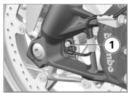
- Remove screw 1 and remove the wheel speed sensor from its bore.
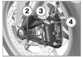
- Disengage the cable for the wheel speed sensor from holding clips 2 and 3.
- Remove mounting bolts 4 from the left and right brake calipers.
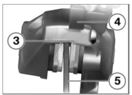
- Force brake pads 3 slightly apart by rocking brake caliper 4 back and forth against brake disc 5.
- Mask off the parts of the wheel rim that could be scratched in the process of removing the brake calipers.
ATTENTION Unwanted inward movement of the brake pads
Component damage on attempt to install the brake caliper or because brake pads have to be forced apart
- Do not operate the brakes with a brake caliper not correctly secured.
- Carefully pull the brake calipers back and out until clear of the brake discs.
- Place the motorcycle on a suitable auxiliary stand.
- with centre stand OE
- Make sure the ground is level and firm and place the motorcycle on its centre stand.
- Raise front of motorcycle until the front wheel can turn freely. Use a
suitable front-wheel stand to lift the front of the motorcycle.
Install the front-wheel stand
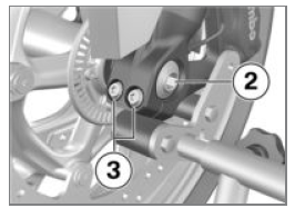
- Remove the axle screw 2.
- Loosen the left axle clamping screws 3.
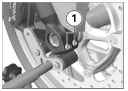
- Loosen the right axle clamping screws 1.
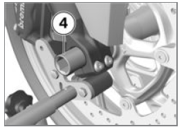
- With the wheel suitably supported, remove axle 4.
- Do not remove the grease from the axle.
- Roll the front wheel forward to remove.
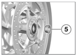
- Remove spacer bush 5 from the left-hand side of the wheel hub.
Installing front wheel
WARNING Use of a non-standard wheel
Malfunction as part of ABS and ASC control interventions
- See the information on the effect of wheel size on the ABS and ASC systems at the start of this chapter.
ATTENTION Tightening threaded fasteners to incorrect tightening torque
Damage, or threaded fasteners work loose
- Always have the security of the fasteners checked by a specialist workshop, preferably an authorised BMW Motorrad dealer.
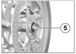
- Slip spacer bush 5, turned with the collar facing out, on to the wheel hub on the left-hand side.
ATTENTION Front wheel installed wrong way round
Risk of accident
- Note direction-of-rotation arrows on tyre or rim.
- Roll the front wheel into position between the forks, making sure that the brake disc passes between the brake pads of the brake caliper on the left.
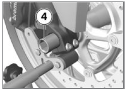
- Raise the front wheel and insert axle 4 until seated.
- Remove front-wheel stand and firmly compress front forks several times. Do not operate the brake lever in this process.
- Install the front-wheel stand.
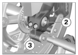
- Install axle screw 2 and tighten to the specified torque.
Counter-hold quick-release axle on the right-hand side.
 Axle screw in front
quick-release axle
- 50 Nm
- Tighten left-hand axle clamping screws 3 to the specified torque.
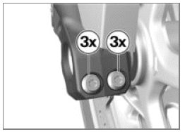
 Clamp of quick-release axle
- Tightening sequence: Tighten screws six times in alternate sequence
- 19 Nm
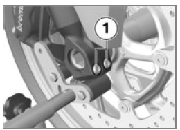
- Tighten right-hand axle clamping screws 1 to torque.
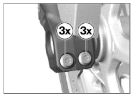
 Clamp of quick-release
axle
- Tightening sequence: Tighten screws six times in alternate sequence
- 19 Nm
- Remove the front-wheel stand.
- Position the right-hand brake caliper on the brake disc.
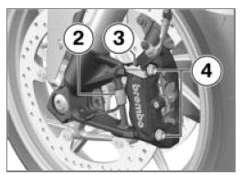
- Tighten mounting bolts 4 of the left and right brake calipers to the specified torque.
 Brake caliper to telescopic fork
- 38 Nm
- Remove the adhesive tape from the wheel rim.
WARNING Brake pads not lying against the brake disc
Risk of accident due to delayed braking effect.
- Before driving, check that the brakes respond without delay.
- Operate the brake several times until the brake pads are bedded.
- Seat the cable for the wheel-speed sensor in holding clips 2 and 3.
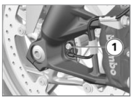
- Insert the wheel speed sensor into the bore and tighten screw 1 to the specified torque.
 Wheel-speed sensor, front, to
fork leg
- Thread-locking compound: micro-encapsulated
- 8 Nm
Removing rear wheel
- Make sure the ground is level and firm and place the motorcycle on a
suitable auxiliary stand.
- with centre stand OE
- Make sure the ground is level and firm and place the motorcycle on its centre stand.
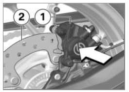
- Press the brake caliper 1 against the brake disc 2.
Brake pistons are pushed back.
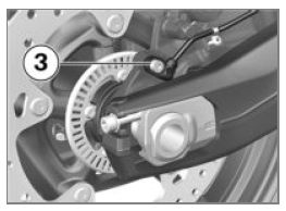
- Remove screw 3 and remove the wheel speed sensor from its bore.
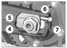
- Remove axle nut 4 and washer 5.
- Back off adjusting screws 7 on both sides.
- Remove chain tensioner 6 and push the axle forward as far as it will go.
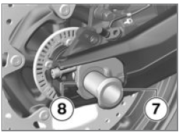
- Remove quick-release axle 7 and remove chain tensioner 8.
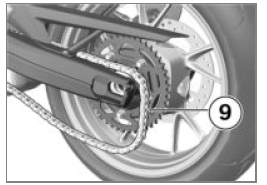
- Roll the rear wheel as far forward as possible and disengage chain 9 from the sprocket.
- Roll the rear wheel back until it is clear of the swinging arm.
NOTICE The sprocket and the spacer bushes on left and right are loose fits in the wheel. Make sure that these parts are not damaged or get lost on removal.
Installing rear wheel
WARNING Use of a non-standard wheel
Malfunction as part of ABS and ASC control interventions
- See the information on the effect of wheel size on the ABS and ASC systems at the start of this chapter.
ATTENTION Tightening threaded fasteners to incorrect tightening torque
Damage, or threaded fasteners work loose
- Always have the security of the fasteners checked by a specialist workshop, preferably an authorised BMW Motorrad dealer.
- Roll the rear wheel into the swinging arm, making sure that the brake disc passes between the brake pads.
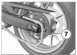
- Roll the rear wheel as far forward as possible and loop chain 7 over the sprocket.
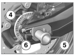
- Insert right chain tensioner 6 into the swinging arm, install quick-release axle 5 in brake caliper carrier 4 and rear wheel.
- Make sure that the axle fits into the recess of the chain tensioner.
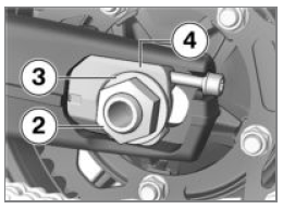
- Insert left-hand chain tensioner 4.
- Install washer 3 and axle nut 2, but do not tighten yet.
- without centre stand OE
- Remove the auxiliary stand.
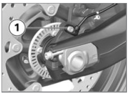
- Insert the wheel speed sensor into the bore and tighten screw 1 to the specified torque.
 Wheel-speed sensor, rear, to
brake caliper carrier
- Thread-locking compound: micro-encapsulated
- 8 Nm
WARNING Brake pads not lying against the brake disc
Risk of accident due to delayed braking effect.
- Before driving, check that the brakes respond without delay.
- After completing work, operate the brake several times until the brake pads are bedded.
- Check chain sag.
- Adjust the chain sag
Trim panel
Removing tank cover
- Remove the seat.
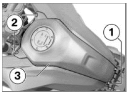
- Remove screws 1 on left and right.
- Remove screws 2.
- Work tank cover 3 up to release it from the retaining lugs and remove.
Installing tank cover
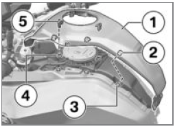
- Make sure that all six holders 2 engage in retaining lugs 3 and that all four connectors 5 engage in securing clips 4.
- Install tank cover 1.
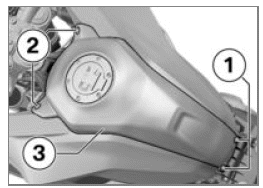
- Install screws 2.
- Install screws 1.
- Install the seat.
See also:
 BMW F900XR - Owner's Manual > Brake system
Checking operation of the brakes Operate the brake lever. The pressure point must be clearly perceptible. Press the footbrake lever. The pressure point must be clearly perceptible.
 BMW F900XR - Owner's Manual > Air filter
Removing air filter Remove the seat. Remove the tank cover. Unclip hose 1 from retaining lugs 2. To unlock, press button 3 in direction of arrow 1 and hold it in this position. Pull frame 4 in direction of arrow 2 out of the holder. Remove frame 4. Remove air filter insert 5.

 Benelli Imperiale 400
 BMW F900XR
 Honda CB500X
 KTM 390 Adventure
 Triumph Street Triple S
 Yamaha MT-03
 Kawasaki Z400
 Triumph Street Triple S
 Yamaha MT-03