 Kawasaki Z400 - Service manual > Throttle Sensor (Service Code 11) (DTC W12Q, W123)
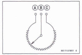
The throttle sensor is a rotating variable resistor that change output voltage according to throttle operating.
The ECU senses this voltage change and determines fuel injection quantity, and ignition timing according to engine rpm, and throttle opening.
Input Terminal [A]: G
Output Terminal [B]: Y/W
Ground Terminal [C]: BR/BK
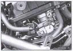
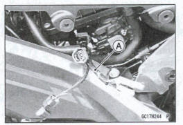
Throttle Sensor Removal/Adjustment
NOTICE
Do not remove or adjust the throttle sensor [A] since it has boon adjusted and set with precision at the factory.
Never drop the throttle body assy especially on a hard surface. Such a shock to the throttle sensor can damage it.
Throttle Sensor Input Voltage Inspection
NOTE
Be sure the battery is fully charged.
Turn the ignition switch off.
Remove:
- Right Side Cover (see Side Cover Removal in the Frame chapter)
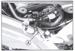
Disconnect the throttle sensor connector and connect the setting adapter [A] between these connectors.
Specia1 Tool - Throttle Sensor Setting Adapter: 57001-1538
Connect a digital meter to the setting adapter leads.
Throttle Sensor put Voltage Connections to Adaptor:
Digital Meter (+) → BK (sensor G) had
Digital Meter (-) → W (sensor BR/BK) lead
Measure the input voltage with the engine stopped and with the connector joined.
Turn the ignition witch on.
Input Voltage Standard: DC 4.75 - 5.25 V
- Turn the ignition switch off.
If the reading is within the standard, check the throttle sensor resistance (see Throttle Sensor Resistance Inspection).
If the reading is out of the standard, remove the ECU and check the wiring for continuity between main harness connectors.
- Disconnect the ECU and sensor connectors.
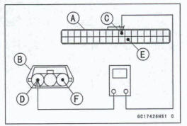
Wiring Continuity Inspection
ECU Connector [A] ←→ Throttle Sensor Connector [B]
ECU Terminal 10 [C] ←→Sensor Terminal [D]
ECU Terminal 28 [El ←→ Sensor Terminal [F]
If the wiring is good, check the ECU for its ground and power supply (see ECU Power Supply Inspection)
If the ground and power supply are good, replace the ECU (see ECU Removal/ Installation ).
Throttle Sensor Resistance Inspection
- Turn the ignition switch off.
- Remove: Right Side Cover (see Side Cover Removal in the Frame chapter)
- Disconnect the throttle sensor connector.
- Connect the setting adapter [A] to the sensor connector only.
Special Tool - Throttle Sensor Setting Adapter: 57001 -1 538
- Measure the throttle sensor resistance.
Throttle Sensor Resistance
Connections to Adapter:
BK (sensor G) lead ←→ W (sensor BR/ BK ) lead
Standard: 4-6k 
If the reading is out of the standard, replace the throttle body assy (see Throttle Body Assy Removal/Installation).
If the reading is within the standard, check the output voltage (see Throttle Sensor Output Voltage Inspection).
Throttle Sensor Output Voltage Inspection
Measure the output voltage at the throttle sensor in the same way as input voltage inspection, note the following.
Disconnect the throttle sensor connector and connect the setting adapter [A] between these connectors.
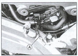
Special Tool - Throttle Sensor Setting Adapter: 57001 -1 538
Throttle Sensor Output Voltage Connections to Adapter:
Digital Meter (+) + R (sensor Y/W) lead
Digital Meter (-) 4 W (sensor BR/BK) lead
- Start the engine and warm it up thoroughly.
- Check idle speed to ensure the throttle opening is correct (see Idle Speed Inspection in the Periodic Maintenance chapter)
Idle Speed Standard: 1 300 +-50 r/min (rpm)
- Turn the ignition switch off.
- Measure the output voltage with the engine stopped and with the connector joined.
- Turn the ignition switch on
Output Voltage
Standard: DC 1 .00 ~1.02 V at idle throttle opening DC 4.07 ~ 4.55 V at full throttle opening (for reference
NOTE
- Open the throttle, confirm the output Wage will be raise.
- The standard voltage refers to the value when the voltage reading at the Input Voltage Inspection shows 5 V exactly.
- When the input voltage reading shows other than 5 V, derive a voltage range as follows.
Example: In the case of a input voltage of 4.75 \/:
1.00 x 4.75+5.00=0.950 V
1.02 x 4.75 + 5.00 = 0.969 V
Thus, the valid range is 0.950 - 0.969 V
Turn the ignition switch of
If the reading is out of the standard, replace the throttle body assy (see Throttle Body Assy Removal/ Installation).
If the reading is within the standard, remove the ECU and check the wiring for continuity between main harness connectors.
- Disconnect the ECU and sensor connectors
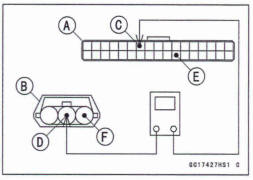
Wiring Continuity Inspection
ECU Connector [A] ←→ Throttle Sensor Connector [B]
ECU Terminal 7 [C]←→ Sensor Terminal [D]
ECU Terminal 28 [E] ←→ Sensor Terminal [F]
If the wiring is good, check the ECU for its ground and power supply (see ECU Power Supply Inspection).
If the ground and power supply are good, replace the ECU (see ECU Removal/Installation).
Throttle Sensor Circuit
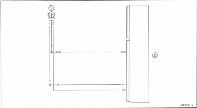
- Throttle Sensor
- ECU
See also:
 Kawasaki Z400 - Service manual > Self-Diagnosis
Self-Diagnosis Outline The self-diagnosis system is monitoring the following mechanisms. DFI System and Ignition System The d-diagnosis system has two modes and can be switched to another mode by operating the meter unit.
Kawasaki Z400 - Service manual > Intake Air Pressure Sensor (Service Code 12) (DTC P0105, P0106, P0107)
Intake Air Pressure Sensor Removal NOTICE Never drop the Intake air pressure sensor especially on a hard surface. Such a shock to the sensor can damage it. Remove: Air Cleaner Housing (see Air Cleaner Housing Removal) Disconnect: Intake Air Pressure Sensor Connector [A] Remove the intake air pressure sensor; [B] from the bracket [C]. Disconnect the vacuum hose [A]. Remove the rubber damper [B] from the intake air pressure sensor [C].
 Benelli Imperiale 400
 BMW F900XR
 Honda CB500X
 KTM 390 Adventure
 Triumph Street Triple S
 Yamaha MT-03
 Kawasaki Z400
 Triumph Street Triple S
 Yamaha MT-03