 Triumph Street Triple S - Service manual > System Diagnostics
The engine management system has an on-board diagnostics feature which allows service technicians to retrieve stored data from the ECM using the Triumph diagnostic software. Full details of the Triumph diagnostic software operation and how to interpret the results are given in the Triumph Diagnostic Tool User Guide.
The software is connected, via an interface cable, to the motorcycle using a dedicated diagnostic plug situated beneath the seats. By using a dedicated plug, no electrical connectors associated with the system are disturbed, reducing potential connector damage.
The software allows the user to retrieve data associated with the system sensors and actuators, test various component functions, read build data and make minor adjustments to the set-up of the system. The data and tests available are described on the following pages.
On-board Fault Detection System
The on-board diagnostic system has two stages to fault detection. When a fault is detected, the DSM (Diagnostic Status Manager) raises a flag to indicate that a fault is present and increments a counter. The counter checks the number of instances that the fault is noted. For example, if there is a fault in the crankshaft position sensor, the counter will increment its count each time the crankshaft turns through 360º, provided the fault is still present.
When the count begins, the fault is detected but not confirmed. If the fault continues to be detected and the count reaches a pre-determined threshold, the fault becomes confirmed. If the fault is an emissions related fault or a serious malfunction affecting engine performance, a DTC (Diagnostic Trouble Code) and freeze-frame data will be logged in the ECM's memory and the MIL (Malfunction Indicator Lamp) on the motorcycle instrument panel is illuminated. Once a fault is confirmed, the number of warm-up cycles made by the engine is counted. If the fault clears, the warm-up cycle counter will extinguish the MIL (Malfunction Indicator Lamp) at a pre determined count, and erase the DTC and freeze frame data from the ECM memory at another (higher) count.
A single warm-up cycle is deemed to have taken place when the following criteria have been met:
- The coolant temperature must be raised to 72º C or more.
- The coolant temperature must have risen by 23º C or more from its start temperature, when 72º C is reached.
- A controlled power-down sequence must take place.
Note:
- When a fault has been rectified, the MIL will remain illuminated until sufficient non-fault warm-up cycles have taken place to turn it off. The MIL will be immediately extinguished if, after first rectifying the fault, the DTC (diagnostic trouble code) that caused the MIL illumination is erased from the ECM memory using the Triumph diagnostic software.
Note:
- In most cases, when a fault is detected, the engine management system will revert to a 'limp-home' mode. In this mode, the engine will still function though the performance and fuel economy may be marginally affected. In some cases, the rider may not notice any appreciable difference from normal operation.
Diagnostic Tool Connection
1. To connect the Triumph diagnostic interface to the motorcycle, Remove the rider's seat and release the diagnostic connector from its locating tang.
2. Plug the diagnostic interface directly in to the diagnostic connector.
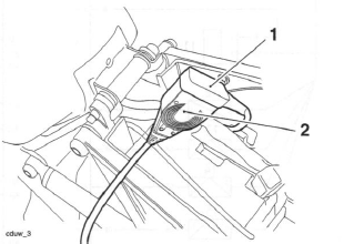
- Diagnostic connector (Daytona 675 shown)
- Diagnostic interface
3. When the diagnostic session is completed, disconnect the Triumph diagnostic interface.
4. Refit the diagnostic connector to its locating tang and refit the rider's seat.
Triumph Diagnostic Software
Described on the following pages is the range of information which can be retrieved from the ECM's memory and the adjustments which can be performed using the Triumph diagnostic software.
The tables indicate which tests are performed by the on-board system and what information can be retrieved by the Triumph diagnostic software.
Note:
- Full details of how to operate the software and how to interpret the data can be found in the Triumph Diagnostic Tool User Guide, which can be downloaded by authorised Triumph dealers from www.triumphonline.net.
Build Data
The Build Data screen will display the following information:
- Motorcycle model;
- Vehicle Identification Number (VIN);
- ECM type;
- ECM ID;
- ECM serial number;
- Tune number;
- Date of last tune download;
- Total tune downloads since manufacture;
- The lock status of the ECM (ECM Locked, Unlocked or Not Applicable).
Current Data
The data available under Current Data is:
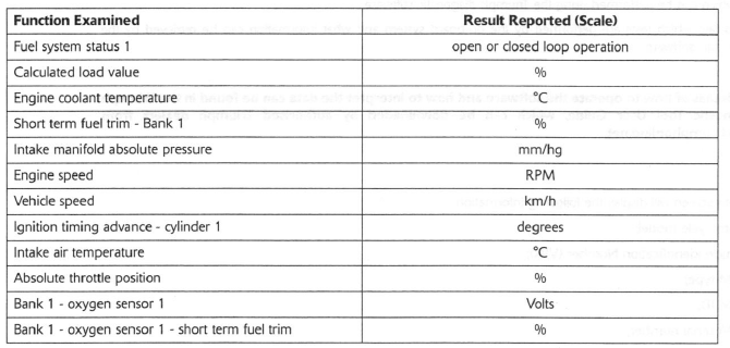
Sensor Data
When using this function it is possible to check the status of various sensors and actuators.
The data sets are divided into seven groups - Sensor Voltages; Sensor Readings; Injector Data; Ignition Data; Idle Speed, Throttle Data and Inputs and Adaption Status. Each of these screens is described on the following pages.
Sensor Voltages
The data available under sensor voltages is:
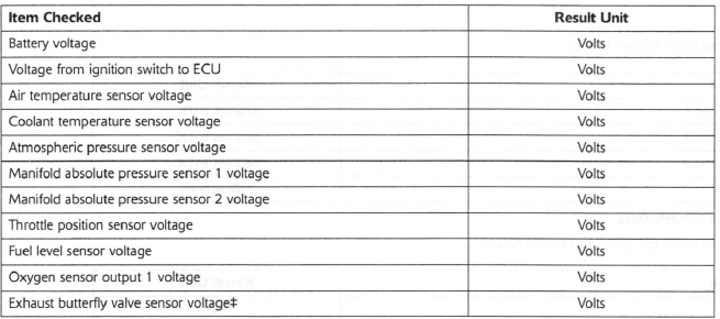
 Applies to models fitted with an exhaust butterfly valve only. All other models
will show Not Applicable in this field.
Sensor Readings
The data available under sensor readings is:
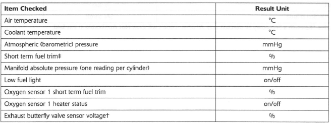
 Applies to models fitted with an exhaust butterfly valve only. All other models
will show Not Applicable in this field.
Injector Data
The data available under injector data is:

Ignition Data
The data available under ignition data is:

Idle Speed and Throttle Data
The data available under idle speed and throttle data is:

 Applies to models fitted with a Secondary air injection only. All other models
will show Not Applicable in this field.
Sensor Data
When using this function it is possible to check the status of various sensors and actuators.
The data sets are divided into seven groups - Sensor Voltages; Sensor Readings; Injector Data; Ignition Data; Idle Speed, Throttle Data and Inputs and Adaption Status. Each of these screens is described on the following pages.
Sensor Voltages
The data available under sensor voltages is:
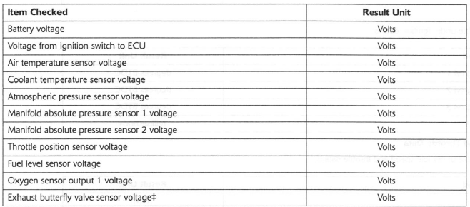
 Applies to models fitted with an exhaust butterfly valve only. All other models
will show Not Applicable in this field.
Sensor Readings
The data available under sensor readings is:
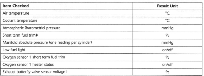
 Applies to models fitted with an exhaust butterfly valve only. All other models
will show Not Applicable in this field.
Injector Data
The data available under injector data is:

Ignition Data
The data available under ignition data is:

Idle Speed and Throttle Data
The data available under idle speed and throttle data is:

 Applies to models fitted with a Secondary air injection only. All other models
will show Not Applicable in this field.
Inputs
The data available under inputs is:
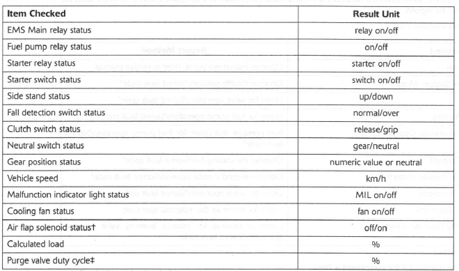
 Applies to models fitted with an intake air flap only. All other models will
show Not Applicable in this field.
 Applies to models fitted with a purge valve only. All other models will show Not
Applicable in this field.
Adaption Status
Because the fuel system is adaptive, the engine management system is able to automatically adjust to new working conditions, such as changes in altitude, component wear, air leaks etc. This screen displays information on the adaption status of the vehicle which will show if it has adapted or not.

Function Tests
The system allows the diagnostic software to perform a series of function tests on various actuators in the engine management system. In some cases it is necessary to make a visual observation of a component and in others, if faults are present, DTCs will be logged.
The function tests available are:
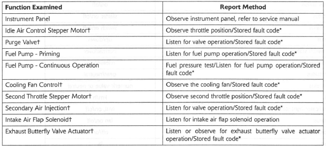
* If a fault is detected.
 Test will only be displayed if the component is fitted.
Instrument Panel Function Test
On the diagnostic software navigate to and select the 'FUNCTION TESTS' option.
Click the start button and observe the instruments for the following:
-
tachometer needle move to 7,500 rpm;
-
the neutral indicator and fuel warning with the malfunction indicator light (MIL) lights alternate on and off;
-
coolant temperature increments up to maximum temperature;
-
coolant warning light illuminates when coolant temperature gauge is at maximum;
-
end of test. Instruments return to normal operation.
Adjust Tune
Using the Triumph diagnostic software, it is possible to:
-
reset the adaptions;
-
balance the throttle bodies.
Further functions are provided to allow correct replacement and adjustment of the:
-
throttle position sensor;
-
idle speed control stepper motor.
These functions are needed as, after replacement of the parts concerned, adjustments have to be made to specific Voltage settings, with the throttles set in a specific position.
Freeze-frame Data
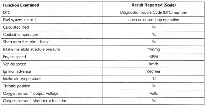
Freeze frame data is stored at the time a DTC is recorded (confirmed) by the ECM. If multiple DTCs are recorded, the freeze-frame data which is stored will relate to the first recorded DTC only.
By calling up freeze frame data associated with the first recorded DTC, the technician can check the engine condition at the time the fault occurred. The data available is:
Diagnostic Trouble Codes
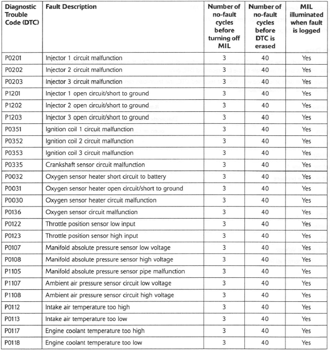
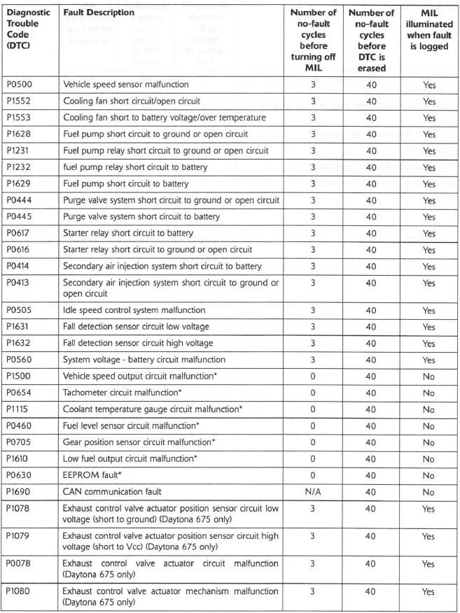
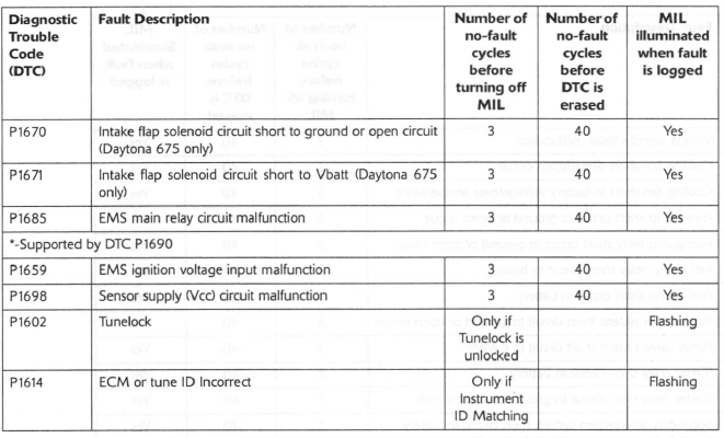
Diagnostic trouble codes (DTCs) are logged in the ECM memory when there is a confirmed fault in the system The codes are reported to the Triumph diagnostic software as a four digit code.
As mentioned earlier, when the system detects a fault, it begins to count the number of times the fault occurs before illuminating the MIL and storing a fault code.
Similarly, if a fault clears, the ECM also records this fact and will turn off the MIL when sufficient no-fault warm-up cycles have taken place. Any fault codes will remain in the ECM memory until the required number of no-fault warm-up cycles have taken place. The number of warm-up cycles required to extinguish the MIL will always be less than the number required to remove a DTC from the ECM memory. DTCs can be removed at any time using the Triumph diagnostic software.
The system will log the diagnostic trouble codes listed below/over:
See also:
 Triumph Street Triple S - Service manual > Engine Management System
System Description The Daytona 675, Street Triple and Street Triple R models are fitted with an electronic engine management system which encompasses control of both ignition and fuel delivery. The electronic control module (ECM) draws information from sensors positioned around the engine, cooling and air intake systems and precisely calculates ignition advance and fueling requirements for all engine speeds and loads.
 Triumph Street Triple S - Service manual > Electrical Connectors
Before beginning any diagnosis, the following connector related information should be noted: Note: A major cause of hidden electrical faults can be traced to faulty electrical connectors. For example: Dirty/corroded terminals. Damp terminals. Broken or bent cable pins within multi-plugs.

 Benelli Imperiale 400
 BMW F900XR
 Honda CB500X
 KTM 390 Adventure
 Triumph Street Triple S
 Yamaha MT-03
 Kawasaki Z400
 Triumph Street Triple S
 Yamaha MT-03