 Triumph Street Triple S - Service manual > Swinging Arm
Removal
Warning: If the engine has recently been running, the exhaust system will be hot. Before working on or near the exhaust system, allow sufficient time for the exhaust system to cool as touching any part of a hot exhaust system could cause burn injuries.
Warning: Before starting work, ensure the motorcycle is stabilised and adequately supported. This will help prevent it from falling and causing injury to the operator or damage to the motorcycle.
1. Remove the seats.
2. Disconnect the battery, negative (black) lead first.
3. Remove the rear panel(s).
4. Daytona 675 only: Remove the lower fairings.
5. Remove the exhaust system.
6. Remove the rear wheel.
7. Support the swinging arm and remove the rear suspension unit.
8. Remove the sprocket cover.
9. Detach the chain from the output sprocket.
Warning: Do not allow the caliper to hang on the brake hose as this may damage the hose and could lead to an accident.
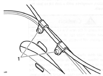
10. Release the brake hose clips from the swinging arm and tie the rear brake caliper to one side.
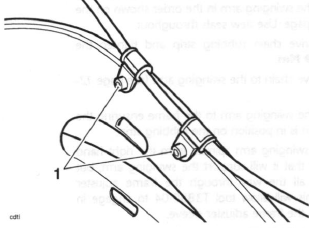
- Rear brake hose clips
11. Remove and discard the swinging arm spindle nut.
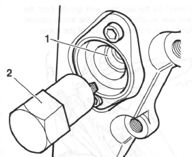
12. Partially withdraw the swinging arm spindle from the right hand side, to allow access to the frame adjuster sleeve located on the left hand side of the frame.
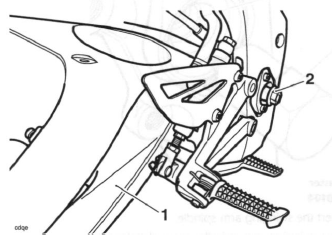
- Swinging arm
- Spindle
13. Engage tool T3880104 in the slots of the frame adjuster sleeve and rotate anti-clockwise to slacken the sleeve fully.
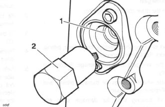
- Frame adjuster sleeve
- Tool T3880104
14. Withdraw the swinging arm spindle from the right hand side and remove the swinging arm, together with the drive chain.
- Support the drive chain while the swinging arm is being removed to protect it from contamination.
- If the swinging arm is to be replaced remove the drive chain.
15. Remove the bearing sleeves from both sides.
16. Remove the right hand bearing by drifting through from the left.
17. Collect the spacer tube.
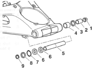
- Frame adjuster sleeve
- Sleeve
- Seal
- Needle roller bearing
- Spacer tube
- Ball Bearing
- Circlip
- Seal
- Spacer
Note:
- The needle roller bearing in the left hand side of the arm cannot be removed undamaged.
18. Remove the drive chain rubbing strip.
Inspection
1. Check all swinging arm bearings for damage, pitting, and cracks. Replace as necessary.
2. Check the swinging arm for damage. Replace as necessary.
3. Check the wheel bearings for damage, pitting, and cracks. Replace as necessary.
4. Check all bearing seals for damage, splits etc.
Replace as necessary.
5. Check the chain for wear, damage etc. Replace as necessary.
6. Check both sprockets for wear, damage etc. Replace as necessary.
7 Check the drive chain rubbing strip for wear and damage. Replace as necessary.
Assembly
1. Install the bearings (marked faces outwards), sleeves etc. into the swinging arm in the order shown on the previous page. Use new seals throughout.
2. Fit the drive chain rubbing strip and tighten the fixing to 9 Nm.
3. Fit the drive chain to the swinging arm.
4. Position the swinging arm to the frame ensuring the drive chain is in position on the rubbing strip.
5. Refit the swinging arm spindle from the right hand side such that it will support the swinging arm, but not pass all the way through the frame adjuster sleeve. This will allow tool T3880104 to engage in the slot in the frame adjuster sleeve.
6. Using tool T3880104, tighten the frame adjuster sleeve to 6 Nm.
- Frame adjuster
- Tool T3880104
7. Fully insert the swinging arm spindle.
8. Fit a new swinging arm spindle nut and tighten to 110 Nm.
9. Fit the drive chain to the output sprocket.
10. Refit the sprocket cover and tighten the bolts to 9 Nm.
11. Release the caliper and refit the rear brake hose clips to the swinging arm. Tighten the fixings to 6 Nm.
- Rear brake hose clips
12. Refit the rear suspension unit.
13. Refit the rear wheel.
14. Refit the exhaust system.
15. Daytona 675 only: Refit the lower fairings.
16. Fit the rear panel(s).
17 Connect the battery, red (positive) lead first.
18. Fit the seats.
19. Pump the rear brake pedal several times to position the brake pads in the caliper. Rectify as necessary if correct brake operation is not restored.
Warning: It is dangerous to operate the motorcycle with defective brakes; you must have your authorised Triumph dealer take remedial action before you ride the motorcycle again. Failure to take remedial action may result in reduced braking efficiency leading to loss of motorcycle control and an accident.
Drive Chain Replacement
Rivet link type
As the drive chain passes through the swinging arm casting, the chain must be split for removal from the motorcycle. Removal of the swinging arm is not required for drive chain replacement. The following instructions for the replacement of rivet link type drive chains requires the use of service tool T3880027
Warning: Before starting work, ensure the motorcycle is stabilised and adequately supported. This will help prevent it from falling and causing injury to the operator or damage to the motorcycle.
1. Support the motorcycle on a stand so the rear wheel is clear of the ground.
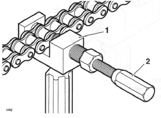
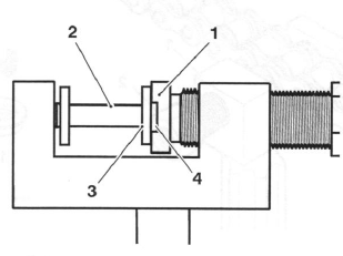
2. Insert the hollow chain cutting tail piece into the tool body so its larger diameter end is facing towards the large pressure screw as shown.
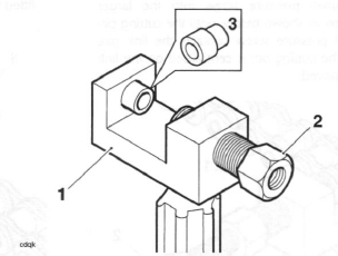
- Tool T3880027
- Large pressure screw
- Chain cutting tail piece
3. Position the chain to the tool ensuring that the chain link pin which is to be removed is aligned with the holes in the chain cutting tail piece and the large pressure screw. Tighten the large pressure screw by hand to grip the chain.
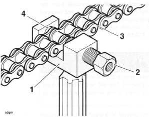
- Tool T3880027
- Large pressure screw
- Chain
- Chain cutting tail piece
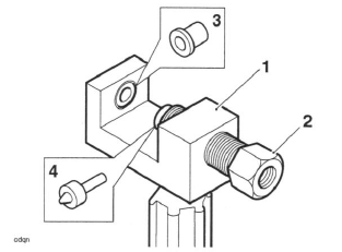
4. Insert the small pressure screw into the larger pressure screw as shown below, until the cutting pin on the small pressure screw contacts the link pin.
Ensure that the cutting pin is centralised on the link pin to be removed.
- Tool T3880027
- Small pressure screw
5. Retain the tool body then tighten the small pressure screw until the link pin is pressed out from the chain.
6. Repeat steps 3 to 5 on the remaining chain link pin.
7. Remove the tool and separate the two ends of the chain.
8. Remove the chain cutting tail piece from the body.
Note:
- The replacement chain is supplied in a split condition, complete with a link kit to join the two ends.
Caution: The component parts of the new link kit are coated with a special grease which must not be removed. Removal of this special grease will severely reduce the service life of the chain.
9. Use the old drive chain to pull the new chain into position as follows: Temporarily attach the end of the new chain to a free end of the old chain using the old connector link. Carefully pull the other end of the old chain to pull the new chain around the sprockets.
Note:
- Do not use the new connector link as the special grease on it may be removed.
10. Using the new link supplied with the chain kit, join the two ends of the chain. Ensure that the O-rings are positioned as shown below and the link plate is fitted with its markings facing outwards.
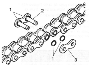
- O-rings
- Link
- Link plate
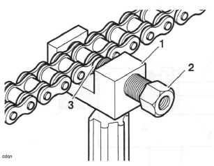
11. Insert the riveting tail piece into the tool body so its larger diameter end is facing towards the large pressure screw as shown.
Note:
- Tool T3880027 includes two link plate holders, one is for riveted link plates (marked PH5O60R), the other is for link plates retained by a spring clip (marked PH4060C). The holder for riveted link plates has a shallow groove to allow for chain link clearance, the holder for clipped link plates has a deep groove to allow for chain link clearance.
12. Insert the link plate holder (marked PH5060R) into the large pressure screw.
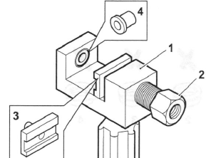
- Tool body
- Large pressure screw
- Link plate holder (marked PH5060R)
- Riveting tail piece
13. Position the tool to the chain. Ensure the link plate holder is correctly located in the large pressure screw.
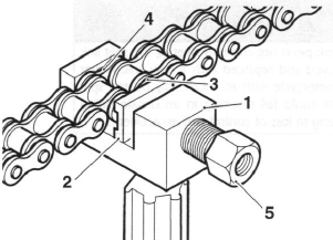
- Tool body
- Link plate holder (marked PH5060R)
- Link plate
- Link
- Large pressure screw
14. Locate the split link pins such that the pins will enter the groove in the link plate holder when the link plate is pressed on to the link.
- Link plate holder
- Link plate
- Chain link
- Link plate holder groove
15. Retain the tool body and tighten the large pressure screw until the link plate is pressed fully onto the link.
16. Back off the pressure screw, slide the tool assembly to one side and check that the split link is correctly assembled.
17. Remove the link plate holder from the tool. Do not remove the riveting tail piece from the tool 18. Insert the flare pin into the large pressure screw.
- Tool body
- Large pressure screw
- Riveting tail piece
- Flare pin
19. Locate one of the split link pins into the riveting tail piece and screw the large pressure screw in until the flare pin contacts the split link end. Ensure the split link pin is centrally located on the flare pin.
20. Retain the tool body and tighten the large pressure screw until the split link end is riveted-over.
- Tool body
- Large pressure screw
- Flare pin
21. Back off the large pressure screw and rivet the remaining split link pin as described above.
22. Remove the tool from the chain and check that both the split link pins are correctly riveted as shown below.
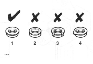
- Correct riveting
- Insufficient riveting
- Excessive riveting
- Riveting off-centre
Warning: If either split link pin is not correctly riveted, the split link must be removed and replaced with a new link. Never operate the motorcycle with an incorrectly riveted split link as the link could fail resulting in an unsafe riding condition leading to loss of control and an accident.
See also:
 Triumph Street Triple S - Service manual > Drive Chain
For safety and to prevent excessive wear, the drive chain must be checked, adjusted and lubricated in accordance with scheduled maintenance requirements. Checking, adjustment and lubrication must be carried out more frequently for extreme conditions such as salty or heavily gritted roads.
Triumph Street Triple S - Service manual > Front Suspension
Exploded View - Front Fork - Daytona 675 and Street Triple R
 Benelli Imperiale 400
 BMW F900XR
 Honda CB500X
 KTM 390 Adventure
 Triumph Street Triple S
 Yamaha MT-03
 Kawasaki Z400
 Triumph Street Triple S
 Yamaha MT-03