 Yamaha MT-03 - Service manual > Steering head
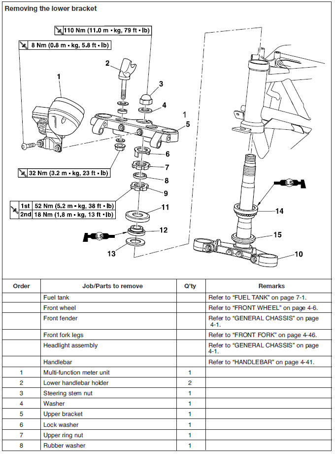
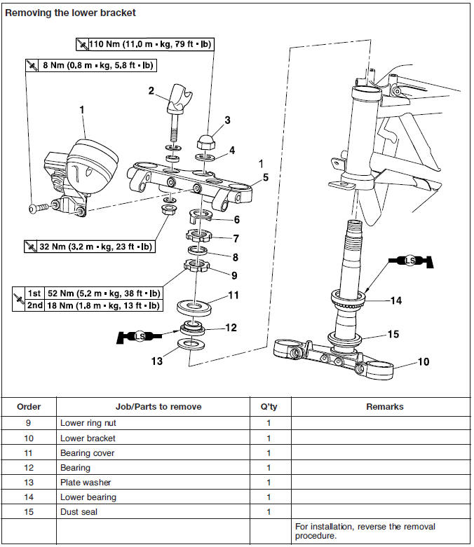
Removing the lower bracket
1. Stand the motorcycle on a level surface.
WARNING
Securely support the motorcycle so that there is no danger of it falling over.
2. Remove:
- Steering stem nut
- Washer
- Upper bracket
- Lock washer
- Upper ring nut "1"
- Rubber washer
- Lower ring nut "2"
- Lower bracket
NOTE:
Hold the lower ring nut with the steering nut wrench "3", and then remove the upper ring nut with the ring nut wrench "4".
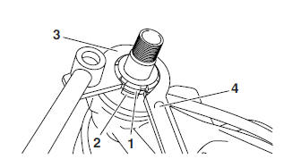
 Steering nut wrench
90890-01403
Ring nut wrench
90890-01268
Steering nut wrench
90890-01403
Ring nut wrench
90890-01268
WARNING
Securely support the lower bracket so that there is no danger of it falling.
Checking the steering head
1. Wash:
- Bearings
- Bearing races
 Recommended cleaning solvent
Kerosene
Recommended cleaning solvent
Kerosene
2. Check:
- Bearings balls "1"
- Bearing races "2"
Damage/pitting → Replace.
3. Replace:
- Bearings
- Bearing races
a. Remove the bearing races "1" from the steering head pipe with a long rod "2" and hammer.
b. Remove the bearing race "3" from the lower bracket with a floor chisel "4" and hammer.
c. Install a new dust seal and new bearing races.
CAUTION:
If the bearing race is not installed properly, the steering head pipe could be damaged.
NOTE:
- Always replace the bearings and bearing races as a set.
- Whenever the steering head is disassembled, replace the dust seal.
4. Check:
- Upper bracket
- Lower bracket (along with the steering stem)
- Bends/cracks/damage → Replace.
Installing the steering head
1. Lubricate:
- Upper bearing
- Lower bearing
- Bearing races
 Recommended lubricant
Lithium-soap-based grease
Recommended lubricant
Lithium-soap-based grease
2. Install:
- Lower ring nut
3. Adjust:
- Steering head
a. Tighten the lower ring nut "1" to the specified torque with a steering nut wrench "2".
NOTE:
Set the torque wrench at a right angle to the steering nut wrench.
 Steering nut wrench
90890-01403
Steering nut wrench
90890-01403
 Lower ring nut
(initial tightening torque)
52 Nm (5.2 m*kg, 38 ft*lb)
Lower ring nut
(initial tightening torque)
52 Nm (5.2 m*kg, 38 ft*lb)
b. Loosen the lower ring nut completely, and then tighten it to the specified torque.
WARNING
Do not overtighten the lower ring nut.
 Lower ring nut
(final tightening torque)
18 Nm (1.8 m*kg, 13 ft*lb)
Lower ring nut
(final tightening torque)
18 Nm (1.8 m*kg, 13 ft*lb)
c. Check the steering head for looseness or binding by turning the front fork all the way in both directions. If any binding is felt, remove the lower bracket and check the upper and lower bearings.
Refer to "CHECKING THE STEERING HEAD".
d. Install the rubber washer "2".
e. Install the upper ring nut "3".
f. Finger tighten the upper ring nut "3", and then align the slots of both ring nuts. If necessary, hold the lower ring nut and tighten the upper ring nut until their slots are aligned.
g. Install the lock washer "1".
NOTE:
Make sure the lock washer tabs "a" sit correctly in the ring nut slots "b".
4. Install:
- Upper bracket
- Washer
- Steering stem nut
5. Install:
- Front fork legs
Refer to "INSTALLING THE FRONT FORK LEGS".
NOTE:
Temporarily tighten the lower bracket pinch bolts.
6. Tighten:
- Steering stem nut
 Steering stem nut
110 Nm (11.0 m*kg, 79 ft*lb)
Steering stem nut
110 Nm (11.0 m*kg, 79 ft*lb)
7. Tighten:
- Upper bracket pinch bolts
 Upper bracket pinch bolt
28 Nm (2.8 m*kg, 20 ft*lb)
Upper bracket pinch bolt
28 Nm (2.8 m*kg, 20 ft*lb)
8. Install:
- Handlebar
- Upper handlebar holders
 Upper handlebar holder bolt
23 Nm (2.3 m*kg, 17 ft*lb)
Upper handlebar holder bolt
23 Nm (2.3 m*kg, 17 ft*lb)
- Handlebar holder caps
Rear shock absorber assembly
Handling the rear shock absorber
WARNING
This rear shock absorber contains highly compressed nitrogen gas. Before handling the rear shock absorber, read and make sure you understand the following information.
The manufacturer cannot be held responsible for property damage or personal injury that may result from improper handling of the rear shock absorber.
- Do not tamper or attempt to open the rear shock absorber.
- Do not subject the rear shock absorber to an open flame or any other source of high heat. High heat can cause an explosion due to excessive gas pressure.
- Do not deform or damage the rear shock absorber in any way. Rear shock absorber damage will result in poor damping performance.
Disposing of a rear shock absorber
1. Gas pressure must be released before disposing of a rear shock absorber. To release the gas pressure, drill a 2-3 mm (0.079- 0.118 in) hole through the rear shock absorber at a point 15-20 mm (0.6-0.8 in) from its end as shown.
WARNING
Wear eye protection to prevent eye damage from released gas or metal chips.
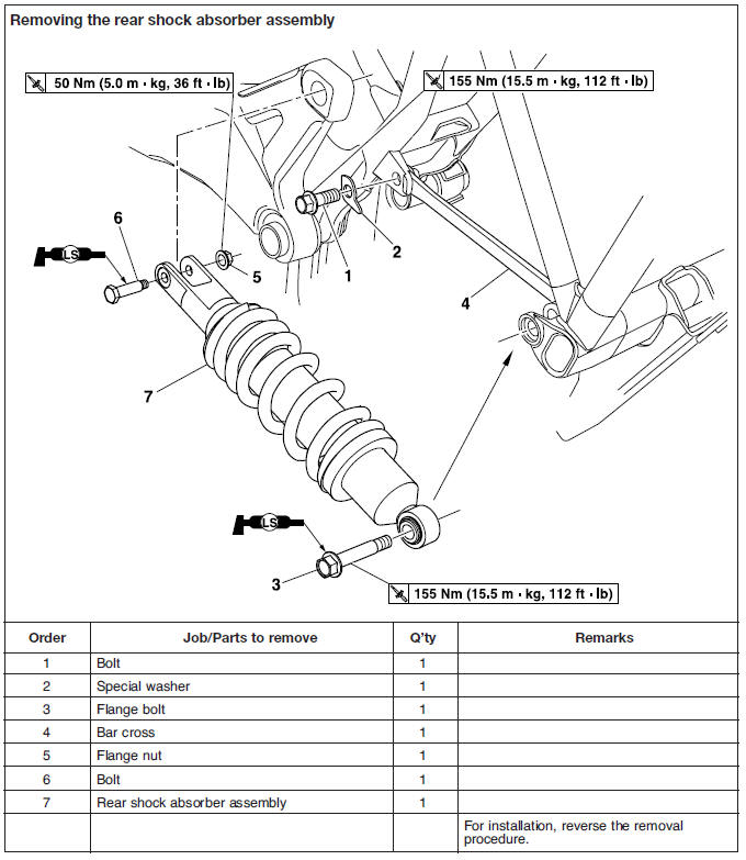
Removing the rear shock absorber assembly
1. Stand the vehicle on a level surface.
WARNING
Securely support the vehicle so that there is no danger of it falling over.
NOTE:
Place the vehicle on a suitable stand so that the rear wheel is elevated.
Checking the rear shock absorber assembly
1. Check:
- Rear shock absorber rod.
Bends/damage → Replace the rear shock absorber assembly.
- Rear shock absorber.
Gas leaks/oil leaks → Replace the rear shock absorber assembly.
- Spring.
Damage/wear → Replace the rear shock absorber assembly.
- Bolts.
Bends/damage/wear → Replace.
Installing the rear shock absorber assembly
1. Lubricate:
- Flange bolt
- Bolt
 Recommended lubricant
Lithium-soap-based grease
Recommended lubricant
Lithium-soap-based grease
2. Install:
- Rear shock absorber assembly "1" (onto the swingarm)
- Bolt "2"
- Flange nut "3"
NOTE:
Tighten the flange nut until just touching. Do not fully tighten the nut.
3. Install:
- Rear shock absorber assembly "1" (into the frame support bracket)
- Flange bolt "4"
- Bar cross "5"
NOTE:
Tighten the flange bolt into the bar cross until just touching. Do not fully tighten the bolt.
4. Install:
- Special washer "6" (into the bolt "7")
NOTE:
Take care of placing the special washer in the correct side and tighten the bolt into the bar cross until just touching.
5. Tighten:
- Flange nut "3"
 Rear shock absorber assembly
nut (rear side)
50 Nm (5.0 m*kg, 36 ft*lb)
Rear shock absorber assembly
nut (rear side)
50 Nm (5.0 m*kg, 36 ft*lb)
- Flange bolt "4"
 Rear shock absorber assembly
bolt (front side)
155 Nm (15.5 m*kg, 112 ft*lb)
Rear shock absorber assembly
bolt (front side)
155 Nm (15.5 m*kg, 112 ft*lb)
6. Rotate:
- Special washer "6" (clockwise until clearance with the abutment is completely recovered)
7. Tighten:
- Bolt "7" (keep the special washer in its position with one finger)
 Bar cross rear bolt
155 Nm (15.5 m*kg, 112 ft*lb)
Bar cross rear bolt
155 Nm (15.5 m*kg, 112 ft*lb)
See also:
 Yamaha MT-03 - Service manual > Swingarm
Removing the swingarm
 Benelli Imperiale 400
 BMW F900XR
 Honda CB500X
 KTM 390 Adventure
 Triumph Street Triple S
 Yamaha MT-03
 Kawasaki Z400
 Triumph Street Triple S
 Yamaha MT-03