 Kawasaki Z400 - Service manual > General Information
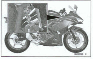
EMISSION CONTROL INFORMATION
To protect the environment in which we all live, Kawasaki has incorporated crankcase emission (1) and exhaust emission (2) control systems in compliance with applicable regulations of the United States Environmental Protection Agency and California Air Resources Board. Additionally, Kawasaki has incorporated an evaporative emission control system (3) in compliance with applicable regulations of the California Air Resources Board on vehicles sold in California only.
1. Crankcase Emission Control System
This system eliminates the release of crankcase vapors into the atmosphere. Instead, the vapors are routed through an oil separator to the intake side of the engine. While the engine is operating, the vapors are drawn into combustion chamber, where they are burned along with the fuel and air supplied by the fuel injection system.
2. Exhaust Emission Control System
This system reduces the amount of pollutants discharged into the atmosphere by the exhaust of this motorcycle. The fuel, ignition, and exhaust systems of this motorcycle have been carefully designed and constructed to ensure an efficient engine with low exhaust pollutant levels.
The exhaust system of this model motorcycle manufactured primarily for sale in California includes a catalytic converter system.
3. Evaporative Emission Control System
Vapors caused by fuel evaporation in the fuel system are not vented into the atmosphere. Instead, fuel vapors are routed into the running engine to be burned, or stored in a canister when the engine is stopped. I The Clean Air Act, which is the Federal law covering motor vehicle pollution, contains what is commonly referred to as the Act's "tampering provisions." Sec. 203(a) The following acts and the causing thereof are prohibited.
(3)(A) for any person to remove or render inoperative any device or element of design installed on or in a motor vehicle or motor vehicle engine in compliance with regulations under this title prior to its sale and delivery to the ultimate purchaser, or for any manufacturer or dealer knowingly to remove or render inoperative any such device or element of design after such sale and delivery to the ultimate purchaser.
(3)(B) for any person engaged in the business of repairing, servicing, selling, leasing, or trading motor vehicles or motor vehicle engines, or who operates a fleet of motor vehicles knowingly to remove or render inoperative any device or element of design installed on or in a motor vehicle or motor vehicle engine in compliance with regulations under this title following its sale and delivery to the ultimate purchaser. .."
NOTE
The phrase "remove or render inoperative any device or element of design" has been generally interpreted as follows.
- Tampering does not include the temporary removal or rendering inoperative of devices or elements of design in order to perform maintenance.
- Tampering could include.
- Maladjustment of vehicle components such that the emission standards are exceeded.
- Use of replacement parts or accessories which adversely affect the performance or durability of the motorcycle.
- Addition of components or accessories that result in the vehicle exceeding the standards.
- Permanently removing, disconnecting, or rendering inoperative any component or element of design of the emission control systems.
TAMPERING WITH NOISE CONTROL SYSTEM PROHIBITED
Federal law prohibits the following acts or the causing thereof. (1) The removal or rendering inoperative by any person other than for purposes of maintenance, repair, or replacement, of any device or element of design incorporated into any new vehicle for the purpose of noise control prior to its sale or delivery to the ultimate purchaser or while it is in use, or (2) the use of the vehicle after such device or element of design has been removed or rendered inoperative by any person.
Among those acts presumed to constitute tampering are the acts listed below.
- Replacement of the original exhaust system or muffler with a component not in compliance with Federal regulations.
- Removal of the muffler(s) or any internal portion of the muffler(s).
- Removal of the air box or air box cover.
- Modifications to the muffler(s) or air intake system by cutting, drilling, or other means if such modifications result in increased noise levels.
Foreword
This manual is designed primarily for use by trained mechanics in a properly equipped shop.
However, it contains enough detail and basic information to make it useful to the owner who desires to perform his own basic maintenance and repair work. A basic knowledge of mechanics, the proper use of tools, and workshop procedures must be understood in order to carry out maintenance and repair satisfactorily. Whenever the owner has insufficient experience or doubts his ability to do the work, all adjustments, maintenance, and repair should be carried out only by qualified mechanics.
In order to perform the work efficiently and to avoid costly mistakes, read the text, thoroughly familiarize yourself with the procedures before starting work, and then do the work carefully in a clean area. Whenever special tools or equipment are specified, do not use makeshift tools or equipment. Precision measurements can only be made if the proper instruments are used, and the use of substitute tools may adversely affect safe operation.
For the duration of the warranty period, we recommend that ail repairs and scheduled maintenance be performed in accordance with this service manual. Any owner maintenance or repair procedure not performed in accordance with this manual may void the warranty.
To get the longest life out of your vehicle.
- Follow the Periodic Maintenance Chart in the Service Manual.
- Be alert for problems and non-scheduled maintenance.
- Use proper tools and genuine Kawasaki Motorcycle parts. Special tools, gauges, and testers that are necessary when servicing Kawasaki motorcycles are introduced by the Service Manual. Genuine parts provided as spare parts are listed in the Parts Catalog.
- Follow the procedures in this manual carefully.
Don't take shortcuts.
- Remember to keep complete records of maintenance and repair with dates and any new parts installed
How to Use This Manual
In this manual, the product is divided into its major systems and these systems make up the manual's chapters. The Quick Reference Guide shows you all of the product's system and assists in locating their chapters. Each chapter in turn has its own comprehensive Table of Contents.
For example, if you want stick coil information, use the Quick Reference Guide to locate the Electrical System chapter. Then, use the Table of Contents on the first page of the chapter to find the Stick Coil section.
Whenever you see symbols, heed their instructions! Always follow safe operating and maintenance practices.
DANGER- indicates a hazardous situation which, if not avoided, will result in death or serious injury.
WARNING- indicates a hazardous situation which, If not avoided, could result I In death or serious injury.
NOTICE
Is used to address practices not related to personal injury.
This manual contains four more symbols which will help you distinguish different types of information.
NOTE
Indicates information that may help or guide you in the operation or service of the vehicle.
- Indicates a procedural step or work to be done
- Indicates a procedural sub-step or how to do the work of the procedural step it follows. It also precedes the text of a NOTE
- Indicates a conditional step or what action to take based on the results of the test or inspection in the procedural step or sub-step it follows.
In most chapters an exploded view illustration of the system components follows the Table of Contents. In these illustrations you will find the instructions indicating which parts require specified tightening torque, oil, grease or a locking agent during assembly.
Before Servicing
Before starting to perform an inspection service or carry out a disassembly and reassembly operation on a motorcycle, read the precautions given below. To facilitate actual operations, notes, illustrations, photographs, cautions, and detailed descriptions have been included in each chapter wherever necessary. This section explains the items that require particular attention during the removal and reinstallation or disassembly and reassembly of general parts.
Especially note the following.
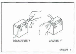
Battery Ground
Before completing any service on the motorcycle, disconnect the battery cables from the battery to prevent the engine from accidentally turning over. Disconnect the ground cable (-1 first and then the positive (+). When completed with the service, first connect the positive (+) cable to the positive (+) terminal of the battery then the negative (-) cable to the negative terminal
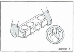
Edges of Parts
Lift large or heavy parts wearing gloves to prevent injury from possible sharp edges on the parts.
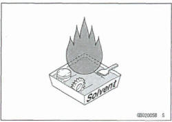
Solvent
Use a high flash-point solvent when cleaning parts. High flash-point solvent should be used according to directions of the solvent manufacturer.
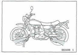
Cleaning Vehicle before Disassembly
Clean the vehicle thoroughly before disassembly. Dirt or other foreign materials entering into sealed areas during vehicle disassembly can cause excessive wear and decrease performance of the vehicle.
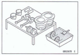
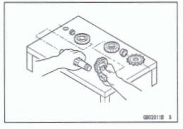
Arrangement and Cleaning of Removed Parts
Disassembled parts are easy to confuse. Arrange the parts according to the order the parts were disassembled and dean the parts in order prior to assembly.
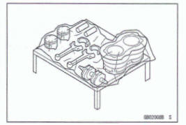
Storage of Removed parts
After all the parts including subassembly parts have been cleaned, store the parts in a clean area. Put a clean cloth or plastic sheet over the parts to protect from any foreign materials that may collect before reassembly.
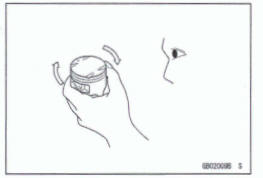
Inspection
Reuse of worn or damaged parts may lead to serious accident.
Visually inspect removed parts for corrosion, discoloration, or other damage. Refer to the appropriate sections of this manual for service limits on individual parts. Replacs the parts if any damage has been found or if the part is beyond its service limit.
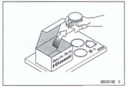
Replacement Parts
Replacement parts must be KAWASAKI genuine or recommended by KAWASAKI. Gaskets, O-rings, oil seals, grease seals, cirdips, cotter pins or self-Iocking nuts must be replaced with new ones whenever disassembled.
Assembly Order
In most cases assembty order is the reverse of disassembly, however, if assembly order is provided in this Service Manual, follow the procedures given.
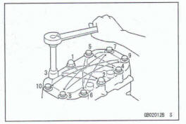
Tightening Sequence
Generally, when installing a part with several bolts, nuts, or screws, start them all in their hdes and tighten them to a snug fit. Then tighten them according to the spedfied se quence to prevent case warpage or deformation which can lead to malfunction. Conversely when loosening the bolts, nuts, or screws, first loosen all of them by about a quarter turn and then remove them. If the specified tightening sequence is not indicated, tighten the fasteners alternating diagonally.
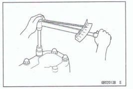
Tightening Torque
Incorrect toque applied to a bolt, nut, or screw may lead to serious damage. Tighten fasteners to the specified toque using a good quality toque wrench.
All of the tightening toque values are for use with dry, solvent - cleaned threads unless otherwise indicated. If a fastener which should have dry, clean threads gets contaminated with lubricant, etc., applying even the specified toque could damage it.
Force
Use common sense during disassembly and assembly, excessive force can cause expensive or hard to repair damage.
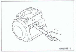
When necessary, remove screws that have a non germanent locking agent applied using an impact driver.
Use a plastic-faced mallet whenever tapping is necessary
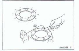
Gasket, O-ring
Hardening, shrinkage, or damage of both gaskets and O-rings after disassembly can reduce sealing performance.
Remove old gaskets and clean the sealing surfaces thoroughly so that no gasket material or other material remains.
Install the new gaskets and replace the used O-rings when re-assembling .
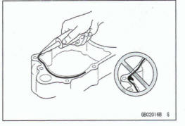
Liquid Gasket, Non-permanent Locking Agent
For applications that require Liquid Gasket or a Non-permanent Locking Agent, clean the surfaces so that no oil residue remains before applying liquid gasket or non-permanent locking agent. Do not apply them excessively.
Excessive application can dog oil passages and cause serious damage.
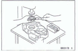
Press
For items such as bearings or oil seals that must be pressed into place, apply small amount of oil to the con- tact area. Be sure to maintain proper alignment and use smooth movements when installing.
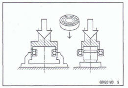
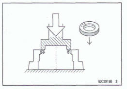
Ball Besring and Needle Bearing
Do not remove pressed ball or needle unless removal is absolutely necessary. Replace with new ones whenever removed. Press bearings with the rnanufacturer and size marks facing out. Press the bearing into place by putting pressure on the correct bearing race as shown.
Pressing the incorrect race can cause pressure between the inner and outer race and result in bearing damage.
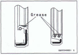
Oil Seal, Grease Seal
Do not remove pressed oil or grease seals unless removal is necessary. Replace with new ones whenever removed.
Press new oil seals with manufacture and size marks facing out. Make sure the seal is aligned properly when installing.
Apply specified grease to the lip of seal before installing the seal.
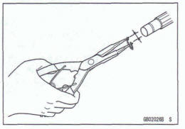
Circlips, Cotter Pins
Replace the circlips or cotter pins that were removed with new ones. Take care not to open the clip excessively when installing to prevent deformation.
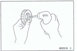
Lubrication
It is important to lubricate rotating or sliding parts during assembly to minimize wear during initial operation. Lubrication points are called out throughout this manual, apply the specific oil or grease as specified.
Direction of Engine Rotation
When rotating the crankshaft by hand, the free play amount of rotating direction will affect the adjustment. Rotate the crankshaft to positive direction (clockwise viewed from output side).
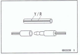
Electrical Wires
A two-color wire is identified first by the primary color and then the stripe color. Unless instructed otherwise, electrical wires must be connected to those of the same color.
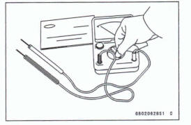
Instrument
Use a meter that has enough accuracy for an accurate measurement. Read the manufacture's instructions thoroughly before using the meter. Incorrect values may lead to improper adjustments.
Handling Electronic Parts
Severe impacts to electronic parts such as the ECU, sensor, and relay can damage them. If dropped on a hard surface, replace such parts with new ones.
If a high voltage that is created by static electricity is applied to the electric parts, it could cause them to fail. To avoid this, touch a non-painted metal surface to discharge any static electricity that is accumulated on your body before inspecting or replacing electric parts.
Be careful not to touch the electrical terminals of the electronic parts. The static electricity discharged from your body could damage them or deform the electrical terminals.
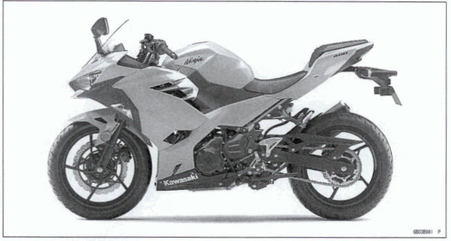
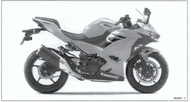
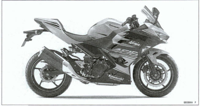
Model Identification
EX400GJ/HJ Left Side View
EX400GJ/HJ Right Side View
EX400JJ Left SideView
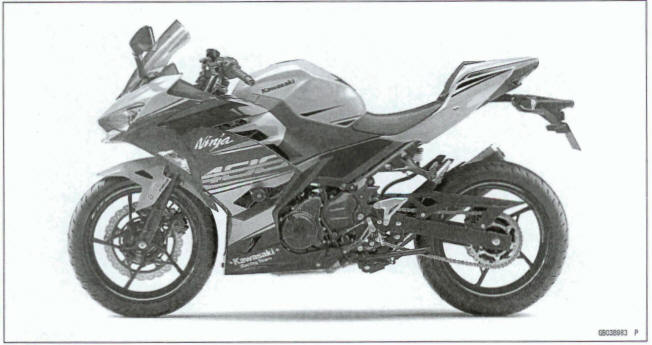
EX400JJ Right Side View
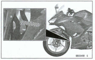
Frame Number
Engine Number
General Specifications
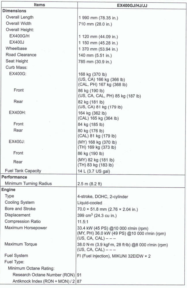
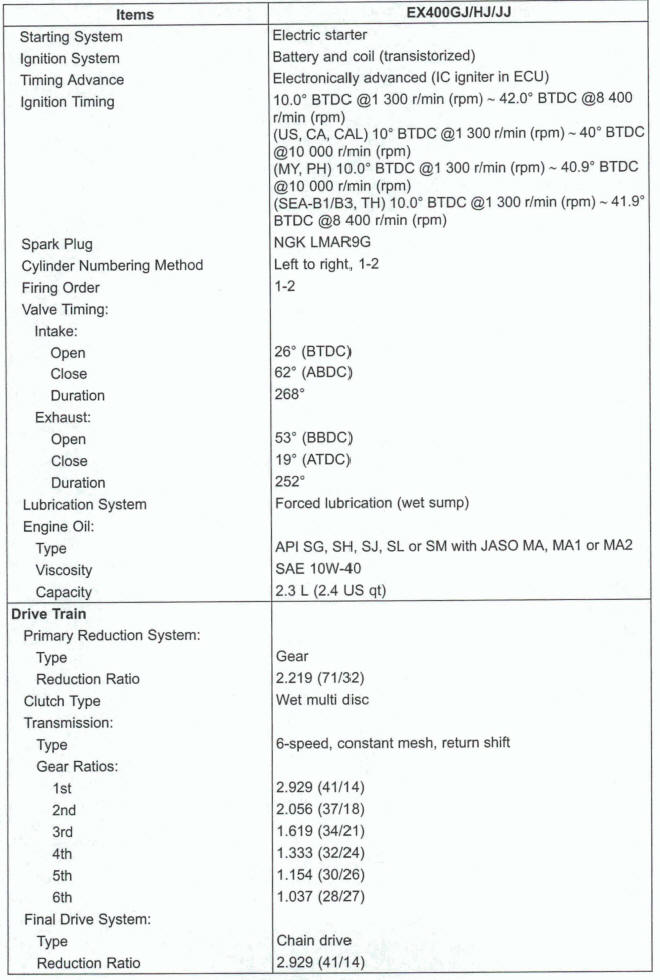
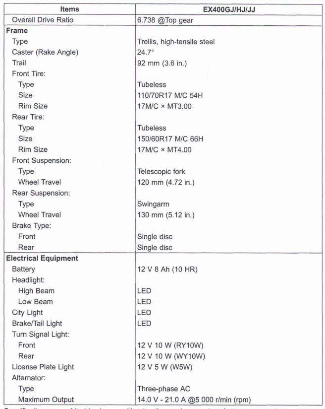
Specifications are subject to change without notice, and may not apply to every country.
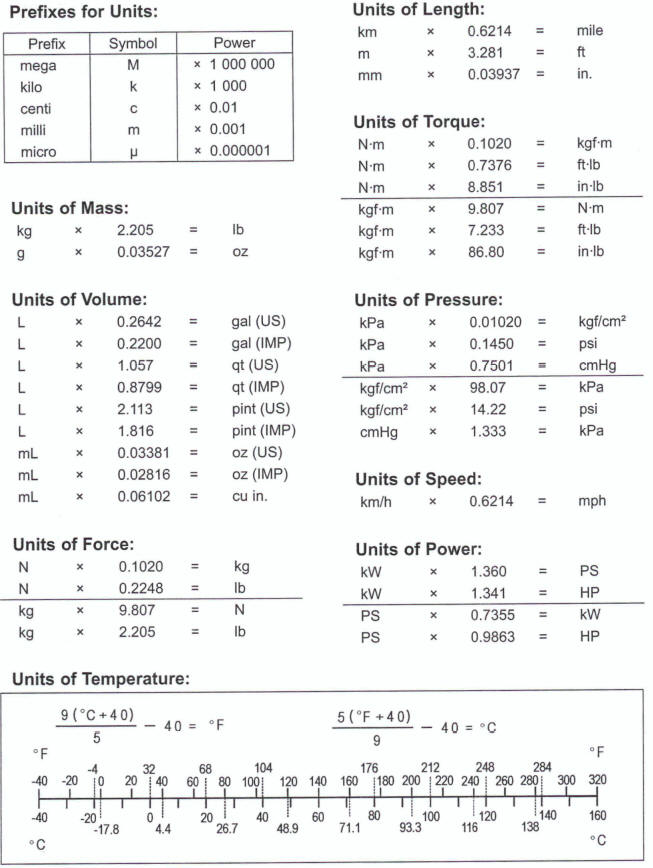
Unit Conversion Table
See also:
 Kawasaki Z400 - Service manual > Periodic Maintenance
Periodic Maintenance Chart The scheduled maintenance must be done in accordance with this chart to keep the motorcycle in good running condition.The Initial maintenance is vitally important and must not be neglected.
 Benelli Imperiale 400
 BMW F900XR
 Honda CB500X
 KTM 390 Adventure
 Triumph Street Triple S
 Yamaha MT-03
 Kawasaki Z400
 Triumph Street Triple S
 Yamaha MT-03