 Triumph Street Triple S - Service manual > Front Suspension/Fork
Front Suspension
The Daytona 675 and street Triple R are equipped with hydraulic, adjustable, telescopic front forks. Both forks are adjustable for spring pre-load, compression damping and rebound damping. From VIN 3 the Daytona 675 front forks have low stroke speed and high stroke speed compression damping adjusters.
The Street Triple is equipped with hydraulic, telescopic front forks. The Street Triple front suspension has no adjustments.
Periodic inspection for damage and fluid leaks is essential for safe riding. Always follow the inspection instructions at the intervals stated in the scheduled maintenance chart.
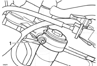
On Daytona 675, a hydraulic, non-adjustable, steering damper is fitted beneath the lower yoke. The damper rod is attached to the frame via a bracket above the radiator.
Fork Inspection
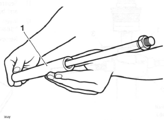
Examine each fork for any sign of damage or scratching of the slider surface or for oil leaks.
If any damage or oil leakage is found, strip and repair as described in this section or consult an authorised Triumph dealer.
Check for smooth operation of the forks as follows:
- Place the motorcycle on level ground.
- While holding the handlebars and applying the front brake, pump the forks up and down several times.
If roughness or excessive stiffness is detected, repair as described in this section or consult an authorised Triumph dealer.
Warning: Riding the motorcycle with defective or damaged suspension can cause loss of motorcycle control and an accident. Never ride with damaged or defective suspension.
Front Fork
Removal
Warning: Before starting work, ensure the motorcycle is stabilised and adequately supported. This will help prevent it from falling and causing injury to the operator or damage to the motorcycle.
1. Raise and support the front of the motorcycle.
2. Remove the front wheel.
3. Release the four fixings and remove the front mudguard.
- Right hand mudguard fixings (Daytona 675 shown)
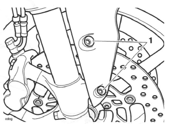
4. Detach and the support the front brake calipers;
Warning: Never allow the brake calipers to hang on the brake hoses as this may damage the hoses. A damaged brake hose can cause a reduction in braking efficiency leading to loss of motorcycle control and an accident.
Note:
- If the forks are to be dismantled, slacken the fork top caps.
5. Daytona 675 only: Slacken the handlebar and top yoke clamp bolts.
- Handlebar clamp bolt
- Top yoke clamp bolt
6. Street Triple and Street Triple R: Slacken the top yoke clamp bolts.
- Top yoke clamp bolt
Caution: Care must be taken when removing the forks, to ensure that the outer surfaces do not become scratched.
7. Slacken the bottom yoke clamp bolts.
Note:
- Daytona 675 shown, Street Triple similar.
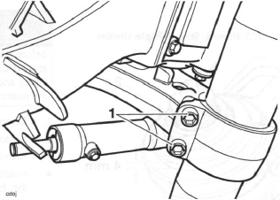
- Bottom yoke clamp bolts
8. Using a downward, twisting action, withdraw the forks from between the yokes.
Installation
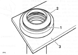
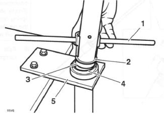
1. Position the forks within the yokes so that the lip of the outer tube, not the top cap, is 4 mm above the upper surface of the top yoke.
Note:
- Daytona 675 shown, Street Triple similar.
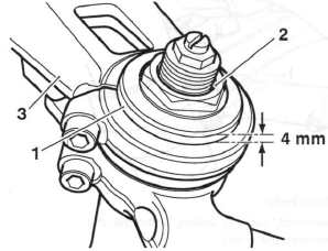
- Outer tube
- Top cap
- Top yoke
2. Tighten the bottom yoke clamp bolts to 20 Nm.
3. Tighten the top yoke clamp bolts to 26 Nm.
4. Daytona 675 only: Tighten the handlebar clamp bolts to 26 Nm.
Note:
- If the forks have been dismantled, tighten the fork top caps to 25 Nm.
5. Refit the front mudguard. Tighten the fixings to 6 Nm.
6. Install the front wheel.
7. Refit the front brake calipers;
8. Lower the motorcycle to the ground and park it on the side stand.
Fork Oil Change
Draining
Warning: Before starting work, ensure the motorcycle is stabilised and adequately supported. This will help prevent it from falling and causing injury to the operator or damage to the motorcycle.
1. Remove the fork.
2. Remove the top cap assembly.
3. Remove the fork spring.
4. Holding the inner and outer tubes together, invert the fork and pour out the fork oil into a suitable container. Pump the damper rod to remove all the oil.
Oil Refilling
The oil level is measured from the upper surface of the fork outer tube, with the fork fully compressed and the spring removed.
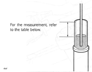
Fork Oil Level (fully compressed)
1. Fill the fork with the grade of oil specified in the fork oil table, to a level above that which will finally be required.
2. Pump the fork assembly and damper several times to expel any trapped air then fully compress the fork and support it in an upright position. Leave the fork for a few minutes to allow the oil to stabilise.
3. Refer to the fork oil level chart and set the scale on tool 3880160-T0301 to the relevant distance, as shown below.
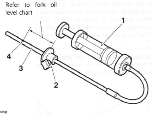
- Tool 3880160-T0301
- Adjustment plate
- Scale area
- Hole (zero position)
Note:
- Zero level on the tool is set at the small exit hole in the side of the scale tube, NOT AT THE END TIP. Do not attempt to block this side hole as this will cause the final fluid level to be incorrect.
4. Insert the scale end of the tool into the fork inner tube.
5. Hold the tool adjuster plate level with the upper surface of the fork inner tube and draw fluid into the syringe until fluid flow ceases (empty the syringe if the body becomes full before fluid flow stops).
6. The fluid level in the fork is now set to the height set on the tool scale. Check the tool scale setting and repeat the process if incorrectly set.
Warning: Incorrect fork oil levels could result in an unsafe riding condition leading to loss of control and an accident.
7. Assemble the fork.
8. Refit the fork.
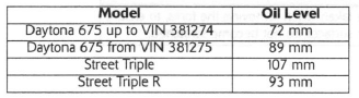
Fork Oil Level Chart
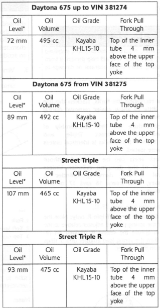
* Fork Fully Compressed
Front Fork
Disassembly
Warning: Before starting work, ensure the motorcycle is stabilised and adequately supported. This will help prevent it from falling and causing injury to the operator or damage to the motorcycle.
Note:
- Before removing the forks, slacken the top cap a little to allow easier removal during strip-down.
- The procedure for the disassembly of Daytona 675, Street Triple and Street Triple R front forks is identical unless otherwise stated.
- The fork seals can be renewed without removal of the damping cylinder. Unless removal of the damping cylinder is necessary, omit items 16 and 17 of this procedure.
1. Remove the forks.
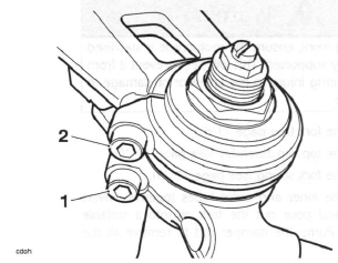
2. Daytona 675 and Street Triple R only: Note the position of the spring preload adjuster relative to the fork cap to ensure the setting is retained on reassembly.
Turn the spring load adjuster until 7 rings are shown on the adjuster.
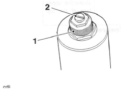
- Preload adjuster marks
- Compression/rebound adjuster
Warning: Do not change the fork adjustment settings. If they are changed, this will change the handling of the motorcycle from those which the rider is used to. Riding with unfamiliar fork settings may cause unexpected handling characteristics leading to loss of motorcycle control and an accident.
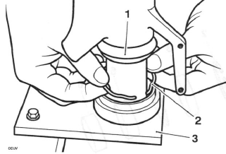
3. Very gently clamp the fork in the soft jawed vice to prevent it from turning, hold the outer tube, then unscrew the top cap from the outer tube.
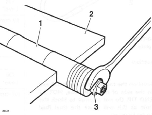
- Fork
- Soft jaws
- Top cap
Caution: Never tightly clamp the outer tube as this will cause the tube to permanently distort. A distorted tube is not serviceable and must be replaced.
Note:
- The top cap is not under spring tension and will not spring upwards when the threads disengage.
4. Holding the inner and outer tubes together, invert the fork and pour out the fork oil into a suitable container. Pump the damper rod to remove all the oil.
5. Return the fork to the soft jawed vice.
Warning: While compressing the fork spring and while the spring holder is in place always wear protective equipment for the face and eyes and never stand directly above or look directly down on the fork. If the spring compressor or holder should dislodge or detach, the resulting release of spring tension could cause parts to fly off resulting in injury to the user.
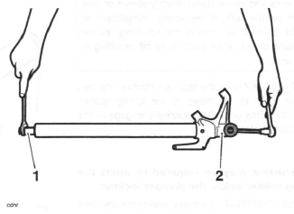
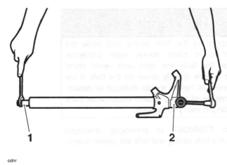
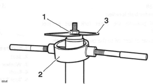
6. Fit tool T3880067 over the top cap. Position the two adjustable arms to the holes in the spring spacer.
Screw in the arms until they positively engage in the spring spacer holes.
Note:
- An assistant may be required to insert the spring holder below the damper locknut.
7. Using tool T3880067, manually compress the fork spring and insert the spring holder as shown, below the damper locknut.
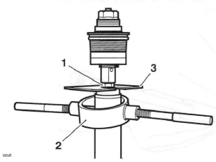
- Damper locknut
- Tool T3880067
- Spring holder (part of T3880067)
8. Slacken the locknut, unscrew and remove the top cap and damper rod. If necessary, remove the O-ring seal from the top cap assembly. The top cap assembly cannot be dismantled.
9. Recompress the fork spring to remove the holder.
Warning: While compressing the fork spring and while the spring holder is in place always wear protective equipment for the face and eyes and never stand directly above or look directly down on the fork. If the spring compressor or holder should dislodge or detach, the resulting release of spring tension could cause parts to fly off resulting in injury to the user.
Note:
- The spring has a smaller coil diameter at its upper end. Note the orientation of the spring before removal.
10. Remove the washer, spring spacer and spring.
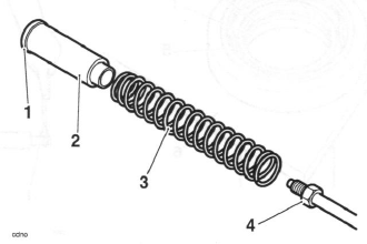
- Washer
- Spring spacer
- Spring
- Damper rod
11. Separate the inner and outer tubes leaving the seals and bushes in place on the outer tube.
12. Invert and mount the fork outer tube to tool T3880002.
13. Remove the dust cover from the outer tube.
- Fork outer tube
- Dust cover
- Tool T3880002
14. Carefully remove the circlip, oil seal and bushes from the outer tube. Note the relative positions of all parts before removal.
- Bush
- Washer
- Oil seal
- Circlip
- Outer tube
- Tool T3880002
Note:
- For Daytona 675 from VIN 381275 only: The tool T3880028 will not fit over the locknut on the damping rod. To use the tool when removing the damper bolt, remove the locknut.
- For Daytona 675 from VIN 381275 only: The locknut for the damper rod is only threaded in the top half of the nut. The lower half of the nut is not threaded and the hole diameter is slightly wider.
15. For Daytona 675 from VIN 381275 only: Remove the locknut from the damper rod. Note the orientation of the locknut for installation.
16. Insert the end of tool T3880028 with the lugs over the damper rod and locknut, if fitted, engage the lugs on the tool into the slots in the damping cylinder inside the fork. Hold the flats of the tool to prevent the cylinder from turning while removing the damper bolt from the bottom of the fork. Discard the washer from the damper bolt.
Note:
- For all models except the Daytona 675 from VIN 381275, the tool T3880028 is designed to fit over the top of the damper rod locknut.
- Tool T3880028
- Damping cylinder bolt location
17. Remove the tool, then the damping cylinder from the inner tube.
- Damping cylinder
Inspection
1. Inspect the inner tube for stone chips, scoring, scratches, excessive wear and any other damage.
Renew as necessary.
Note:
- Small inclusions in the inner tube may be removed using a fine grade stone or similar.
2. Inspect the spring for damage, cracks and deformation. Renew the spring if necessary.
3. Inspect all the bushes and seals for damage. Renew any damaged items if necessary.
Assembly
Warning: The front forks comprise many precision machined parts. Total cleanliness must be observed at all times and assembly must take place in a dirt/dust-free environment.
Dirt ingress may cause damage to the fork parts, leading to incorrect operation, instability, loss of control or an accident.
Note:
- If the damping cylinder has not been removed, omit operations 1 and 2.
1. Fit the damping cylinder to the inner tube and engage tool T3880028 as during removal.
2. Clean the threads of the damping cylinder bolt and fit a new sealing washer. Apply a drop of ThreeBond 1342 to the threads then install the bolt. Prevent the cylinder from turning by holding the flats at the end of tool T3880028 while tightening the damping cylinder securing bolt to 24 Nm.
- Tool T3880028
- Damping cylinder bolt location
3. Invert and position the outer fork tube to tool T3880002.
4. Apply a smear of fork oil to the bushes and seals.
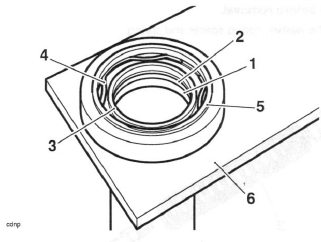
5. Position the seals and lower bush to the inner tube as noted prior to removal. Use a new circlip.
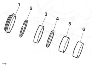
- Dust seal
- Circlip
- Oil seal
- Washer
- Lower bush
- Upper bush
6. Using a suitable tool, fit the upper bush to the outer fork outer tube.
7. Position the inner tube assembly to the outer, ensuring that the oil and dust seal lips do not become damaged.
8. Using the narrow end of tool T3880003, push/tap the bush, washer and seal into position.
- Tool T3880003
- Seal
- Washer
- Bush
- Tool T3880002
9. Retain the bush, washer and seal with the new circlip.
- Dust seal
- Circlip
- Tool T3880002
10. Position the dust seal to the outer tube.
11. Invert tool T3880003 and, using hand pressure only, push the dust seal squarely into the outer tube.
12. Fill the fork with oil.
13. Position the fork assembly as for compression of the fork spring during strip down.
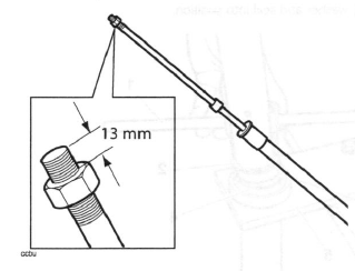
14. Daytona 675 and Street Triple R only: Rethread the damper rod locknut leaving 13 mm of thread exposed above the nut.
15. Street Triple only: Screw the damper rod locknut to the bottom of the damper rod threads.
16. Refit the fork spring, close wound end uppermost, spring spacer and washer.
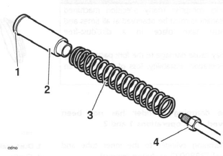
- Washer
- Spring spacer
- Spring
- Damper rod
17. Attach tool 3880085-T0301 to the threads of the damper rod and pull the damper upwards.
Warning: While re-compressing the fork spring and while the spring holder is in place always wear protective equipment for the face and eyes and never stand directly above or look directly down on the fork. If the spring compressor or holder should dislodge or detach, the resulting release of spring tension could cause parts to fly off resulting in injury to the user.
18. Refit tool T3880067 as previously described, compress the fork spring and refit the spring holder.
- Damper locknut
- Tool T3880067
- Spring holder (part of T3880067)
19. Remove tool 3880085-T0301 from the damper rod.
Caution: If removed, the damping rod locknut must be fitted with the flat face facing to the top of the fork. The slightly tapered face must face the fork spring. Incorrect orientation may lead to a loosening of the locknut.
20. Fit a new O-ring to the top cap.
21. Daytona 675 and Street Triple R only: Ensure the damping adjuster rod is installed in to the damper rod.
22. All models: Refit the top cap to the damper rod.
23. Daytona 675 and Street Triple R only: Ensure the damper rod thread is screwed into the top cap to a depth of 13 mm, as set by the locknut at step 14.
24. Street Triple only: Screw the top cap fully on the damper rod.
25. All models: Hold the top cap while tightening the damper rod locknut to 17 Nm.
Warnings: While compressing the fork spring and while the spring holder is in place always wear protective equipment for the face and eyes and never stand directly above or look directly down on the fork. If the spring compressor or holder should dislodge or detach, the resulting release of spring tension could cause parts to fly off resulting in injury to the user.
26. Recompress the spring to remove the spring holder.
27 Lubricate the O-ring on the top cap with a smear of fork oil then screw the top cap fully into the inner tube.
28. Tighten the top cap to 25 Nm.
Note:
- It is much easier to tighten the top cap when the fork has been refitted.
29. Refit the fork.
See also:
 Triumph Street Triple S - Service manual > Front Suspension
Exploded View - Front Fork - Daytona 675 and Street Triple R
Triumph Street Triple S - Service manual > Headstock Bearing Check/Adjustment
Check 1. Raise and support the front of the motorcycle. Warning: Before starting work, ensure the motorcycle is stabilised and adequately supported. This will help prevent it from falling and causing injury to the operator or damage to the motorcycle. Checking Headstock Bearing Adjustment (Daytona 675 shown)
 Benelli Imperiale 400
 BMW F900XR
 Honda CB500X
 KTM 390 Adventure
 Triumph Street Triple S
 Yamaha MT-03
 Kawasaki Z400
 Triumph Street Triple S
 Yamaha MT-03