 Yamaha MT-03 - Service manual > Engine
Adjusting the valve clearance
The following procedure applies to all of the valves.
NOTE:
- Valve clearance adjustment should be made on a cold engine, at room temperature.
- When the valve clearance is to be measured or adjusted, the piston must be at top dead center (TDC) on the compression stroke.
1. Remove:
- Seats
- Fuel tank
- Radiator
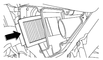
- Air-filter-to-air-cut-off-valve hose
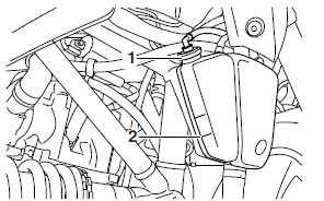
2. Remove:
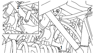
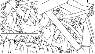
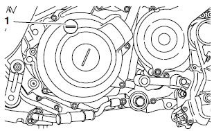
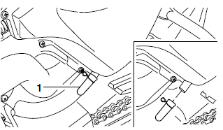
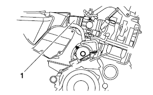
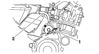
- Intake tappet cover
- Exhaust tappet cover "1"
- Camshaft sprocket cover "2"
3. Disconnect:
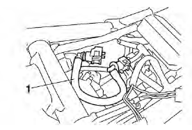
- Spark plug cap "1"
4. Remove:
- Spark plug "2"
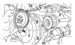
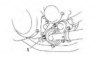
5. Remove:
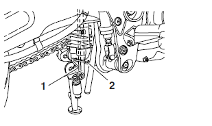
- Timing mark accessing screw "1"
- Crankshaft end accessing screw "2"
6. Valve clearance
- Out of specification → Adjust.
 Valve clearance (cold)
Intake valve
Valve clearance (cold)
Intake valve
0.09-0.13 mm (0.0035-0.0051 in)
Exhaust valve
0.16-0.20 mm (0.0063-0.0079 in)
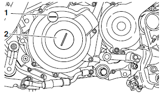
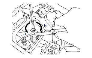
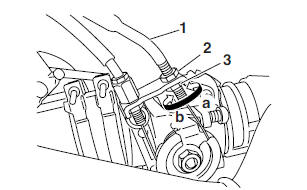
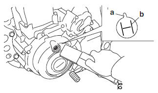
a. Turn the crankshaft counterclockwise.
b. When the piston is at the top dead center (TDC) on the compression stroke, align the "I" mark "a" on the A.C. magneto rotor with the stationary pointer "b" on the A.C. magneto cover.
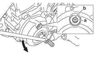
NOTE:
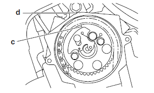
To position the piston at top dead center (TDC) on the compression stroke, align the "I" mark "c" on the camshaft sprocket with the stationary pointer "d" on the cylinder head, as shown in the illustration.
c. Measure the valve clearance with a thickness gauge "1".
Out of specification → Adjust.
 Thickness gauge
90890-03079
Thickness gauge
90890-03079
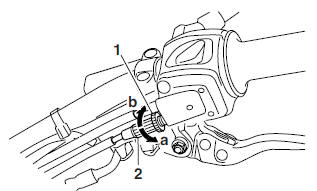
7. Adjust:
- Valve clearance
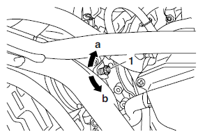
a. Loosen the locknut "1".
b. Insert a thickness gauge "2" between the end of the adjusting screw and the valve tip.
c. Turn the adjusting screw "3" in direction "a" or "b" until the specified valve clearance is obtained.
Direction "a" Valve clearance is increased.
Direction "b" Valve clearance is decreased.
d. Hold the adjusting screw to prevent it from moving and tighten the locknut to the specified torque.
 Locknut
14 Nm (1.4 m*kg, 10 ft*lb)
Locknut
14 Nm (1.4 m*kg, 10 ft*lb)
e. Measure the valve clearance again.
f. If the valve clearance is still out of specification, repeat all of the valve clearance adjustment steps until the specified clearance is obtained.
8. Install:
- Timing mark accessing screw
- Crankshaft end accessing screw
9. Install:
- Spark plug
 Spark plug
13 Nm (1.3 m*kg, 9.4 ft*lb)
Spark plug
13 Nm (1.3 m*kg, 9.4 ft*lb)
10.Connect:
- Spark plug cap
11.Install:
- Camshaft sprocket cover
 Camshaft sprocket cover bolt
10 Nm (1.0 m*kg, 7.2 ft*lb)
Camshaft sprocket cover bolt
10 Nm (1.0 m*kg, 7.2 ft*lb)
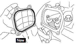
- O-rings "1"

- Intake tappet cover
 Intake tappet cover bolt
10 Nm (1.0 m*kg, 7.2 ft*lb)
Intake tappet cover bolt
10 Nm (1.0 m*kg, 7.2 ft*lb)
- Exhaust tappet cover
 Exhaust tappet cover bolt
10 Nm (1.0 m*kg, 7.2 ft*lb)
Exhaust tappet cover bolt
10 Nm (1.0 m*kg, 7.2 ft*lb)- 12.Install:
- Air-filter-to-air-cut-off-valve hose
- Radiator
- Fuel tank
- Seats
Adjusting the engine idling speed
NOTE:
Prior to adjusting the engine idling speed, the air filter element should be cleaned, and the engine should have adequate compression.
1. Start the engine and let it warm up for several minutes.
2. Check:
Engine idling speed
Out of specification → Adjust.
 Engine idling speed
1300-1500 r/min
Engine idling speed
1300-1500 r/min
3. Adjust:
- Engine idling speed
a. Turn the throttle stop screw "1" in direction "a" or "b" until the specified engine idling speed is obtained.
Direction "a" Engine idling speed is increased.
Direction "b" Engine idling speed is decreased.
4. Adjust:
- Throttle cable free play
 Throttle cable free play
(at the flange of the throttle grip)
3.0-5.0 mm (0.12-0.20 in)
Throttle cable free play
(at the flange of the throttle grip)
3.0-5.0 mm (0.12-0.20 in)
Adjusting the throttle cable free play
NOTE:
Prior to adjusting the throttle cable free play, the engine idling speed should be adjusted properly.
1. Check:
- Throttle cable free play "a"
Out of specification → Adjust.
 Throttle cable free play
(at the flange of the throttle grip)
3.0-5.0 mm (0.12-0.20 in)
Throttle cable free play
(at the flange of the throttle grip)
3.0-5.0 mm (0.12-0.20 in)
2. Adjust:
- Throttle cable free play
NOTE:
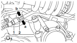
When the throttle is opened, the accelerator cable "1" is pulled.
Throttle body end
a. Loosen the locknut "2" on the accelerator cable.
b. Turn the adjusting nut "3" in direction "a" or "b" until the specified throttle cable free play is obtained.
Direction "a" Throttle cable free play is increased.
Direction "b" Throttle cable free play is decreased.
c. Tighten the locknut.
NOTE:
If the specified throttle cable free play cannot be obtained on the throttle body end of the cable, adjust the free play at the handlebar end of the cable using the adjusting nut.
Handlebar end
a. Loosen the locknut "1".
b. Turn the adjusting nut "2" in direction "a" or "b" until the specified throttle cable free play is obtained.
Direction "a" Throttle cable free play is increased.
Direction "b" Throttle cable free play is decreased.
c. Tighten the locknut.
WARNING
After adjusting the throttle cable free play, start the engine and turn the handlebars to the right and to the left to ensure that this does not cause the engine idling speed to change.
Checking the spark plug
1. Disconnect:
- Spark plug cap
2. Remove:
- Spark plug
CAUTION:
Before removing the spark plug, blow away any dirt accumulated in the spark plug well with compressed air to prevent it from falling into the cylinder.
3. Check:
- Spark plug type
Incorrect → Change.
 Spark plug type
(manufacturer)
CR7E (NGK)
Spark plug type
(manufacturer)
CR7E (NGK)
4. Check:
- Electrode "1"
Damage/wear → Replace the spark plug.
- Insulator "2"
Abnormal color → Replace the spark plug.
Normal color is medium-to-light tan.
5. Clean:
- Spark plug (with a spark plug cleaner or wire brush)
6. Measure:
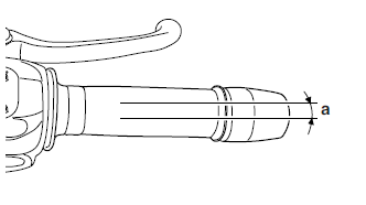
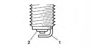
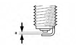
- Spark plug gap "a" (with a thickness gauge) Out of specification → Regap.
 Spark plug gap
0.7-0.8 mm (0.028-0.031 in)
Spark plug gap
0.7-0.8 mm (0.028-0.031 in)
7. Install:
- Spark plug
 Spark plug
13 Nm (1.3 m*kg, 9.4 ft*lb)
Spark plug
13 Nm (1.3 m*kg, 9.4 ft*lb)
NOTE:
Before installing the spark plug, clean the spark plug and gasket surface.
8. Connect:
- Spark plug cap
Checking the ignition timing
NOTE:
Prior to checking the ignition timing, check the wiring connections of the entire ignition system.
Make sure all connections are tight and free of corrosion.
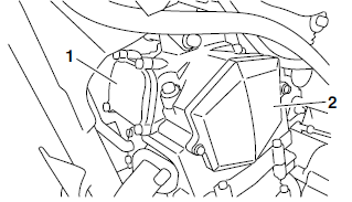
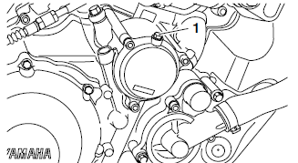
1. Remove:
- Timing mark accessing screw "1"
2. Connect:
- Timing light (onto the spark plug lead)
 Timing light
90890-03141
Timing light
90890-03141
3. Check:
- Ignition timing
a. Start the engine, warm it up for several minutes, and then let it run at the specified engine idling speed
 Engine idling speed
1300-1500 r/min
Engine idling speed
1300-1500 r/min
b. Check that the stationary pointer "a" is within the firing range "b" on the A.C. magneto rotor.
Incorrect firing range → Check the ignition system.
NOTE:
The ignition timing is not adjustable.
4. Detach:
- Timing light
5. Install:
- Timing mark accessing screw
Measuring the compression pressure
NOTE:
Insufficient compression pressure will result in a loss of performance.
1. Measure:
- Valve clearance
Out of specification → Adjust.
2. Start the engine, warm it up for several minutes, and then turn it off.
3. Disconnect:
- Spark plug cap
4. Remove:
- Spark plug
CAUTION:
Before removing the spark plug, blow away any dirt accumulated in the spark plug well with compressed air to prevent it from falling into the cylinder.
5. Install:
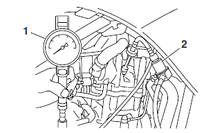
- Compression gauge "1"
- Adaptor (compression gauge) "2"
 Compression gauge
90890-03081
Compression gauge
90890-03081
Adaptor (compression gauge) 90890-04082
6. Measure:
- Compression pressure
Out of specification → Refer to steps (c) and (d).
 Compression pressure
(at sea level)
Compression pressure
(at sea level)
Minimum 600 kPa (6.0 kg/cm2, 85.3 psi)
Standard 650 kPa (6.5 kg/cm2, 92.4 psi)
Maximum 700 kPa (7.0 kg/cm2, 99.6 psi)
a. Set the main switch to "ON" and the engine
stop switch to " ".
".
b. With the throttle wide open, crank the engine until the reading on the compression gauge stabilizes.
WARNING
To prevent sparking, ground the spark plug lead before cranking the engine.
c. If the compression pressure is above the maximum specification, check the cylinder head, valve surfaces, and piston crown for carbon deposits.
Carbon deposits → Eliminate.
d. If the compression pressure is below the minimum specification, pour a teaspoonful of engine oil into the spark plug bore and measure it again.
Refer to the following table. 
7. Install:
- Spark plug
 Spark plug
13 Nm (1.3 m*kg, 9.4 ft*lb)
Spark plug
13 Nm (1.3 m*kg, 9.4 ft*lb)
8. Connect:
- Spark plug cap
Checking the engine oil level
1. Place the vehicle on a level surface and hold it in an upright position.
NOTE:
Make sure that the vehicle is positioned straight up when checking the oil level. A slight tilt to the side can result in a false reading.
2. Start the engine, warm it up for 10-15 minutes, let it continue to idle for 20-30 seconds, and then turn it off.
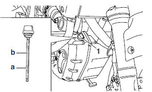
3. Wait a few minutes until the oil settles, remove the engine oil tank dipstick "1", wipe the dipstick clean, insert it back into the oil filler hole (without screwing it in), and then remove it again to check the oil level.
WARNING
The exhaust pipes are very hot during and following operation. To prevent burns when removing the oil filler cap, use extra care not to touch the exhaust pipes.
NOTE:
The engine oil tank is located in front of the frame.
4. Check:
- Engine oil level
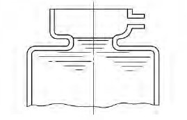
The engine oil level should be between the minimum level mark "a" and maximum level mark "b".
Below the minimum level mark → Add the recommended engine oil to the proper level.
CAUTION:
Do not operate the vehicle until you know that the engine oil level is sufficient.
WARNING
Never remove the engine oil tank cap after high-speed operation, otherwise hot engine oil could spout out and cause damage or injury. Always let the engine oil cool down sufficiently before removing the oil tank cap.
 Recommended oil
Refer to the chart for the engine
oil grade which is best suited
for certain atmospheric temperatures.
Recommended oil
Refer to the chart for the engine
oil grade which is best suited
for certain atmospheric temperatures.
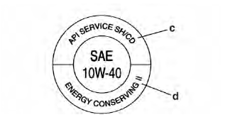
API standard SE, SF, SG or higher
grade. 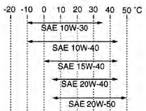
CAUTION:
- Engine oil also lubricates the clutch and the wrong oil types or additives could cause clutch slippage. Therefore, do not add any chemical additives or use engine oils with a grade of CD "c" or higher and do not use oils labeled "ENERGY CONSERVING II" "d" or higher.
- Do not allow foreign materials to enter the crankcase.
5. Install the engine oil tank dipstick.
6. Start the engine, warm it up for several minutes, and then turn it off.
7. Check the engine oil level again.
NOTE:
Before checking the engine oil level, wait a few minutes until the oil has settled.
Changing the engine oil
1. Start the engine, warm it up for several minutes, and then turn it off.
2. Place the motorcycle on its side stand, then place an oil pan under the oil tank and another under the engine to collect the used oil.
3. Remove:
- Engine oil tank dipstick
- Engine oil crankcase drain bolt "1"
- Engine oil tank drain bolt "2"
4. Remove:
- Oil filter element drain bolt "1"
5. Drain:
- Engine oil (completely from the crankcase and the oil tank)
6. If the oil filter element is also to be replaced, perform the following procedure.
a. Remove the oil filter element cover "1" and oil filter element "2".
b. Check the O-rings "3" and replace them if they are cracked or damaged.
c. Install the new oil filter element and the oil filter element cover.
 Oil filter element cover bolt
10 Nm (1.0 m*kg, 7.2 ft*lb)
Oil filter element cover bolt
10 Nm (1.0 m*kg, 7.2 ft*lb)
7. Check:
- Engine oil drain bolt gasket
Damage → Replace.
8. Install:
- Engine oil drain bolt (crankcase) (along with the gasket)
 Engine oil drain bolt
(crankcase)
30 Nm (3.0 m*kg, 22 ft*lb)
Engine oil drain bolt
(crankcase)
30 Nm (3.0 m*kg, 22 ft*lb)
- Engine oil drain bolt (oil tank) (along with the gasket)
 Engine oil drain bolt (oil
tank)
30 Nm (3.0 m*kg, 22 ft*lb)
Engine oil drain bolt (oil
tank)
30 Nm (3.0 m*kg, 22 ft*lb)
- Oil filter element drain bolt
 Oil filter element drain bolt
10 Nm (1.0 m*kg, 7.2 ft*lb)
Oil filter element drain bolt
10 Nm (1.0 m*kg, 7.2 ft*lb)
9. Fill:
- Oil tank (with the specified amount of the recommended engine oil)
CAUTION:
The engine oil tank must be filled with engine oil in two steps. First, fill the engine oil tank with 2.0 L (2.11 Imp qt, 1.75 US qt) of the recommended engine oil. Then, start the engine, race it five or six times, turn it off, and then add the remainder of the engine oil.
 Quantity
Total amount
3.40 L (2.99 Imp qt, 3.60 US qt)
Quantity
Total amount
3.40 L (2.99 Imp qt, 3.60 US qt)
Without oil filter element replacement 3.00 L (2.64 Imp qt, 3.17 US qt)
With oil filter element replacement 3.10 L (2.72 Imp qt, 3.28 US qt)
10.Install:
- Engine oil tank dipstick
11.Start the engine, warm it up for several minutes, and then turn it off.
12.Check:
- Engine (for engine oil leaks)
13.Check:
- Engine oil level
14.Check:
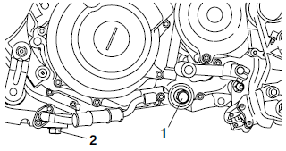
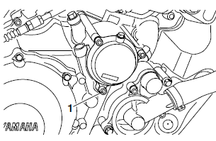
- Engine oil pressure
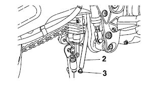
a. Slightly loosen the bleed bolt "1
b. Start the engine and keep it idling until engine oil starts to seep from the bleed bolt. If no engine oil comes out after one minute, turn the engine off so that it will not seize.
c. Check the engine oil passages, the oil filter element, and the oil pump for damage or leakage. Refer to "OIL PUMP" on page 5-41.
d. Start the engine after correcting the problem( s) and check the engine oil pressure again.
e. Tighten the bleed bolt to the specified torque.
 Bleed bolt
5 Nm (0.5 m*kg, 3.6 ft*lb)
Bleed bolt
5 Nm (0.5 m*kg, 3.6 ft*lb)
Adjusting the clutch cable free play
1. Check:
- Clutch cable free play "a"
Out of specification → Adjust.
 Clutch cable free play
(at the end of the clutch lever)
10.0-15.0 mm (0.39-0.59 in)
Clutch cable free play
(at the end of the clutch lever)
10.0-15.0 mm (0.39-0.59 in)
2. Adjust:
- Clutch cable free play
Handlebar end
a. Slide back the rubber cover "3".
b. Loosen the locknut "1".
c. Turn the adjusting bolt "2" in direction "b" or "c" until the specified clutch cable free play is obtained.
Direction "b" Clutch cable free play is increased.
Direction "c" Clutch cable free play is decreased.
d. Tighten the locknut.
e. Slide the rubber cover to its original position.
NOTE:
If the specified clutch cable free play cannot be obtained on the handlebar end of the cable, adjust the free play at the engine end of the cable using the adjusting nut.
Engine end
a. Loosen the locknut "1".
b. Turn the adjusting nut "2" in direction "a" or "b" until the specified clutch cable free play is obtained.
Direction "a" Clutch cable free play is increased.
Direction "b" Clutch cable free play is decreased.
c. Tighten the locknuts
Checking the air filter element
NOTE:
There are two check hoses "1" and "2" at the bottom of the air filter case. Check the hose "1" for accumulated dirt, water or oil. If dirt, water or oil is visible remove the hose, clean it and then install it in its original position. Remove the plug "3" drain any dirt, water or oil and then install it in its original position. If dust and/or water collects in these hoses, clean the air filter element and air filter case.
1. Remove:
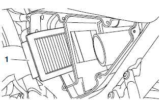
- Air filter case cover "1"
2. Remove:
- Air filter element "1"
3. Check:
- Air filter element
Damage → Replace.
4. Install:
- Air filter element
CAUTION:
Never operate the engine without the air filter element installed. Unfiltered air will cause rapid wear of engine parts and may damage the engine. Operating the engine without the air filter element will also affect the throttle body tuning, leading to poor engine performance and possible overheating.
NOTE:
Insert the air filter element into the air filter case as shown.
5. Install:
- Air filter case cover
Checking the throttle body joint
1. Check:
- Throttle body joint "1"
Cracks/damage → Replace.
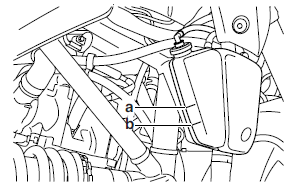
Checking the fuel hose
1. Remove:
- Seats
- Fuel tank
2. Check:
- Fuel hose "1"
Cracks/damage → Replace.
Loose connection → Connect properly.
3. Install:
- Fuel tank
- Seats
Checking the fuel tank breather/overflow hoses
1. Check:
- Fuel tank breather/overflow hoses "1"
Loose connection → Connect properly.
Cracks/damage → Replace.
CAUTION:
- Make sure that the end of the fuel tank breather/overflow hoses is not blocked, and clean it if necessary.
- Make sure that the end of the fuel tank breather/overflow hoses is positioned inside of the clamp "2".
Checking the crankcase breather hoses
1. Check:
- Crankcase-to-crankcase-breather-chamber hose "1"
- Air-filter-to-crankcase-breather-chamber hose "2"
Cracks/damage → Replace.
Loose connection → Connect properly.
CAUTION:
Make sure the breather hoses are routed correctly.
Checking the exhaust system
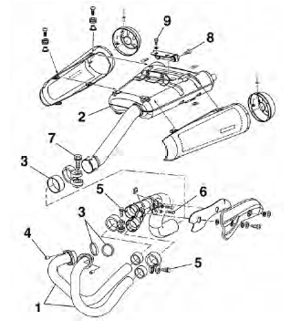
The following procedure applies to all of the exhaust pipes and gaskets.
1. Check:
- Exhaust pipes "1"
- Muffler "2" Cracks/damage → Replace.
- Gaskets "3" Exhaust gas leaks → Replace.
2. Check:
- Tightening torques
 Exhaust pipe nut "4"
20 Nm (2.0 m*kg, 14 ft*lb)
Exhaust pipe nut "4"
20 Nm (2.0 m*kg, 14 ft*lb)
Exhaust pipe joint bolt "5" 18 Nm (1.8 m*kg, 13 ft*lb)
Exhaust pipe and frame bolt "6" 25 Nm (2.5 m*kg, 18 ft*lb)
Exhaust pipe and muffler bolt "7" 18 Nm (1.8 m*kg, 13 ft*lb)
Muffler stay and muffler bolt "8" 22 Nm (2.2 m*kg, 16 ft*lb)
Muffler stay and frame bolt "9" 22 Nm (2.2 m*kg, 16 ft*lb)
Checking the coolant level
1. Stand the motorcycle on a level surface.
NOTE:
- Place the motorcycle on a suitable stand.
- Make sure the motorcycle is upright.
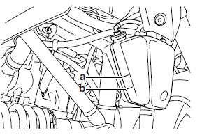
2. Check:
- Coolant level
The coolant level should be between the maximum level mark "a" and minimum level mark "b".
Below the minimum level mark → Add the recommended coolant to the proper level.
CAUTION:
- Adding water instead of coolant lowers the antifreeze content of the coolant. If water is used instead of coolant check, and if necessary, correct the antifreeze concentration of the coolant.
- Use only distilled water. However, if distilled water is not available, soft water may be used.
3. Start the engine, warm it up for several minutes, and then turn it off.
4. Check:
- Coolant level
NOTE:
Before checking the coolant level, wait a few minutes until it settles.
Checking the cooling system
1. Remove:
- Seats
- Fuel tank
2. Check:
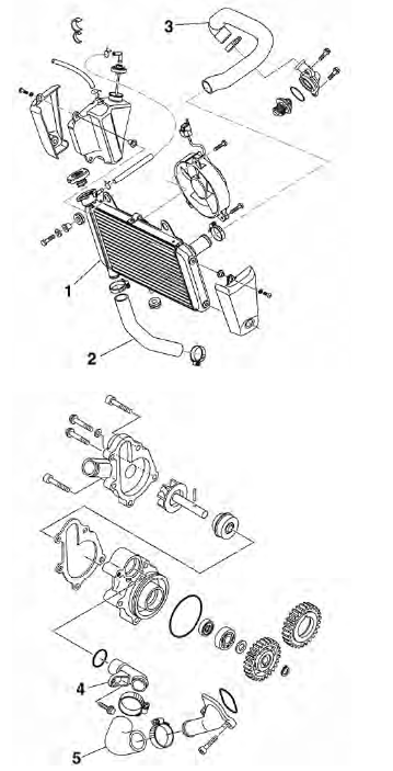
- Radiator "1"
- Radiator outlet hose "2"
- Radiator inlet hose "3"
- Water pump assembly
- Water pump outlet pipe "4"
- Water pump outlet hose "5"
Cracks/damage → Replace
3. Install:
- Fuel tank
- Seats
Changing the coolant
1. Remove:
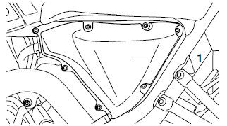
- Panel (right)
2. Remove:
- Radiator cap
WARNING
A hot radiator is under pressure. Therefore, do not remove the radiator cap when the engine is hot. Scalding hot fluid and steam may be blown out, which could cause serious injury. When the engine has cooled, open the radiator cap as follows: Place a thick rag or a towel over the radiator cap and slowly turn the radiator cap counterclockwise toward the detent to allow any residual pressure to escape.
When the hissing sound has stopped, press down on the radiator cap and turn it counterclockwise to remove.
3. Remove:
- Coolant reservoir cap "1"
- Coolant reservoir "2"
4. Drain:
- Coolant (from the coolant reservoir)
5. Install:
- Coolant reservoir
 Coolant reservoir bolt
5 Nm (0.5 m*kg, 3.6 ft*lb)
Coolant reservoir bolt
5 Nm (0.5 m*kg, 3.6 ft*lb)
6. Remove:
- Coolant drain bolt "1" (along with the copper washer)
7. Drain:
- Coolant (from the engine and radiator)
8. Check:
- Copper washer "1"

- Coolant drain bolt "2"
Damage → Replace.
9. Install:
- Coolant drain bolt
 Coolant drain bolt
10 Nm (1.0 m*kg, 7.2 ft*lb)
Coolant drain bolt
10 Nm (1.0 m*kg, 7.2 ft*lb)
10.Fill:
- Cooling system (with the specified amount of the recommended coolant)
 Recommended antifreeze
High-quality ethylene glycol
antifreeze containing corrosion
inhibitors for aluminum engines
Mixing ratio
1:1 (antifreeze:water)
Recommended antifreeze
High-quality ethylene glycol
antifreeze containing corrosion
inhibitors for aluminum engines
Mixing ratio
1:1 (antifreeze:water)
Quantity Total amount 1.00 L (0.88 Imp qt, 1.06 US qt)
Coolant reservoir capacity 0.25 L (0.22 Imp qt, 0.26 US qt)
From minimum to maximum level mark 0.15 L (0.13 Imp qt, 0.16 US qt)
Handling notes for coolant
Coolant is potentially harmful and should be handled with special care.
WARNING
- If coolant splashes in your eyes, thoroughly wash them with water and consult a doctor.
- If coolant splashes on your clothes, quickly wash it away with water and then with soap and water.
- If coolant is swallowed, induce vomiting and get immediate medical attention.
CAUTION:
- Adding water instead of coolant lowers the antifreeze content of the coolant. If water is used instead of coolant, check and if necessary, correct the antifreeze concentration of the coolant.
- Use only distilled water. However, if distilled water is not available, soft water may be used.
- If coolant comes into contact with painted surfaces, immediately wash them with water.
- Do not mix different types of antifreeze.
13.Install:
- Coolant reservoir cap
14.Start the engine, warm it up for several minutes, and then turn it off.
15.Check:
- Coolant level
NOTE:
Before checking the coolant level, wait a few minutes until the coolant has settled.
16.Install:
- Panel (right)
See also:
 Yamaha MT-03 - Service manual > Periodic checks and
Adjustments
Yamaha MT-03 - Service manual > Periodic checks and
Adjustments
Periodic maintenance Introduction This chapter includes all information necessary to perform recommended checks and adjustments. If followed, these preventive maintenance procedures will ensure more reliable vehicle operation, a longer service life and reduce the need for costly overhaul work. This information applies to vehicles already in service as well as to new vehicles that are being prepared for sale. All service technicians should be familiar with this entire chapter.
Yamaha MT-03 - Service manual > Chassis
Adjusting the front brake 1. Adjust: Brake lever position (distance "a" from the throttle grip to the brake lever) a. While pushing the brake lever forward, turn the adjusting dial "1" until the brake lever is in the desired position.
 Benelli Imperiale 400
 BMW F900XR
 Honda CB500X
 KTM 390 Adventure
 Triumph Street Triple S
 Yamaha MT-03
 Kawasaki Z400
 Triumph Street Triple S
 Yamaha MT-03