 Yamaha MT-03 - Service manual > Chassis
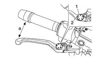
Adjusting the front brake
1. Adjust:
- Brake lever position (distance "a" from the throttle grip to the brake lever)
a. While pushing the brake lever forward, turn the adjusting dial "1" until the brake lever is in the desired position.
NOTE:
Be sure to align the setting on the adjusting dial with the arrow mark "2" on the brake lever holder.
Position #1 Distance "a" is the largest.
Position #5 Distance "a" is the smallest.
WARNING
After adjusting the brake lever position, make sure that the pin on the brake lever holder is firmly inserted in the hole in the adjusting dial.
CAUTION:
After adjusting the brake lever position, make sure that there is no brake drag.
WARNING
A soft or spongy feeling in the brake lever can indicate the presence of air in the brake system. Before the vehicle is operated, the air must be removed by bleeding the brake system. Air in the brake system will considerably reduce braking performance and could result in loss of control and possibly an accident. Therefore, check the brake system and bleed if necessary
Adjusting the rear brake pedal
1. Check:
- Brake pedal position (distance "a" from the top of the rider footrest to the top of the brake pedal) Out of specification → Adjust.
 Brake pedal position (below
the top of the rider footrest)
14.5 mm (0.57 in)
Brake pedal position (below
the top of the rider footrest)
14.5 mm (0.57 in)
2. Adjust:
- Brake pedal position
a. Loosen the locknut "1".
b. Turn the adjusting bolt "2" in direction "b" or "c" until the specified brake pedal position is obtained.
Direction "b" Brake pedal is raised.
Direction "c" Brake pedal is lowered.
c. Tighten the locknut "1" to the specified torque.
 Locknut
18 Nm (1.8 m*kg, 13 ft*lb)
Locknut
18 Nm (1.8 m*kg, 13 ft*lb)
WARNING
A soft or spongy feeling in the brake pedal can indicate the presence of air in the brake system. Before the vehicle is operated, the air must be removed by bleeding the brake system. Air in the brake system will considerably reduce braking performance and could result in loss of control and possibly an accident. Therefore, check and, if necessary, bleed the brake system.
CAUTION:
After adjusting the brake pedal position, make sure there is no brake drag.
Checking the brake fluid level
1. Stand the motorcycle on a level surface.
NOTE:
- Place the motorcycle on a suitable stand..
- Make sure the motorcycle is upright.
2. Check:
- Brake fluid level
Below the minimum level mark "a" →Add the recommended brake fluid to the proper level.
 Recommended brake fluid
DOT 4
Recommended brake fluid
DOT 4
A. Front brake
B. Rear brake
WARNING
- Use only the designated brake fluid. Other brake fluids may cause the piston seals to deteriorate, causing leakage and poor brake performance.
- Refill with the same type of brake fluid that is already in the system. Mixing brake fluids may result in a harmful chemical reaction, leading to poor brake performance.
- When refilling, be careful that water does not enter the brake fluid reservoir. Water will significantly lower the boiling point of the brake fluid and could cause vapor lock.
CAUTION:
Brake fluid may damage painted surfaces and plastic parts. Therefore, always clean up any spilt brake fluid immediately.
NOTE:
In order to ensure a correct reading of the brake fluid level, make sure the top of the brake fluid reservoir is horizontal.
Checking the front and rear brake pads And brake pad pins
The following procedure applies to all of the brake pads.
1. Operate the brake.
2. Check:
- Front brake pads
Wear indicator grooves "1" have almost disappeared → Replace the brake pads as a set.
3. Measure:
- Rear brake pads
Wear limit "2" reached → Replace the brake pads as a set.
 Rear brake pad wear limit
1.0 mm (0.04 in)
Rear brake pad wear limit
1.0 mm (0.04 in)
4. Check:
- Brake pad pins
Damage/wear → Replace.
Checking the front and rear brake hoses
The following procedure applies to all of the brake hoses and brake hose clamps.
1. Check:
- Front brake hoses "1"
- Rear brake hoses "2"
Cracks/damage/wear → Replace.
2. Check:
- Brake hose clamp
Loose → Tighten the clamp bolt.
3. Hold the motorcycle upright and apply the brake several times.
4. Check:
- Brake hoses
Brake fluid leakage → Replace the damaged hose.
Bleeding the hydraulic brake system
WARNING
Bleed the hydraulic brake system whenever:
- the system is disassembled
- a brake hose is loosened, disconnected or replaced
- the brake fluid level is very low
- brake operation is faulty.
NOTE:
- Be careful not to spill any brake fluid or allow the brake master cylinder reservoir or brake fluid reservoir to overflow.
- When bleeding the hydraulic brake system, make sure there is always enough brake fluid before applying the brake. Ignoring this precaution could allow air to enter the hydraulic brake system, considerably lengthening the bleeding procedure.
- If bleeding is difficult, it may be necessary to
let the brake fluid settle for a few hours.
Repeat the bleeding procedure when the tiny bubbles in the hose have disappeared.
1. Bleed:
- Hydraulic brake system
a. Fill the brake fluid reservoir to the proper level with the recommended brake fluid.
b. Install the diaphragm (brake master cylinder reservoir or brake fluid reservoir).
c. Connect a clear plastic hose "1" tightly to the bleed screw.
A. Front brakes
B. Rear brake
d. Place the other end of the hose into a container.
e. Slowly apply the brake several times.
f. Fully pull the brake lever or fully press down the brake pedal and hold it in position.
g. Loosen the bleed screw.
NOTE:
Loosening the bleed screw will release the pressure and cause the brake lever to contact the throttle grip or the brake pedal to fully extend.
h. Tighten the bleed screw, and then release the brake lever or brake pedal.
i. Repeat steps (e) to (h) until all of the air bubbles have disappeared from the brake fluid in the plastic hose.
j. Tighten the bleed screw to the specified torque.
 Bleed screw
6 Nm (0.6 m*kg, 4.3 ft*lb)
(front brake)
14 Nm (1.4 m*kg, 10 ft*lb)
(rear brake)
Bleed screw
6 Nm (0.6 m*kg, 4.3 ft*lb)
(front brake)
14 Nm (1.4 m*kg, 10 ft*lb)
(rear brake)
k. Fill the brake fluid reservoir to the proper level with the recommended brake fluid.
WARNING
After bleeding the hydraulic brake system, check the brake operation.
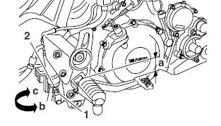
Adjusting the shift pedal
1. Check:
- Shift pedal position (distance "a" from the top of the rider footrest to the top of the shift pedal)
Out of specification → Adjust.
 Shift pedal position (from the
top
of the rider footrest to the top of
the shift pedal)
34.0 mm (1.33 in)
Shift pedal position (from the
top
of the rider footrest to the top of
the shift pedal)
34.0 mm (1.33 in)
2. Adjust:
- Shift pedal position
a. Remove the bolt "1".
b. Remove the shift pedal "2".
c. Install the shift pedal at the correct position.
d. Install the bolt, and then tighten it to the specified torque.
 Shift pedal bolt
20 Nm (2.0 m*kg, 14.7 ft*lb)
LOCTITE 243
Shift pedal bolt
20 Nm (2.0 m*kg, 14.7 ft*lb)
LOCTITE 243
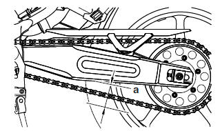
Adjusting the drive chain slack
NOTE:
The drive chain slack must be checked at the tightest point on the chain.
CAUTION:
A drive chain that is too tight will overload the engine and other vital parts, and one that is too loose can skip and damage the swingarm or cause an accident. Therefore, keep the drive chain slack within the specified limits.
1. Stand the motorcycle on a level surface.
WARNING
Securely support the motorcycle so that there is no danger of it falling over.
NOTE:
Both wheels should be on the ground without a rider on the motorcycle.
2. Rotate the rear wheel several times and check the drive chain to locate its tightest point.
3. Measure:
- Drive chain slack "a"
Out of specification → Adjust.
 Drive chain slack
40.0-50.0 mm (1.57-1.97 in)
Drive chain slack
40.0-50.0 mm (1.57-1.97 in)
4. Loosen:
- Wheel axle nut "1"
5. Adjust:
- Drive chain slack
a. Loosen both locknuts "2".
b. Turn both adjusting bolts "3" in direction "a" or "b" until the specified drive chain slack is obtained.
Direction (a) Drive chain is tightened.
Direction (b) Drive chain is loosened.
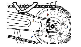
NOTE:
- To maintain the proper wheel alignment, adjust both sides evenly.
- Push the rear wheel forward to make sure that there is no clearance between the swingarm end plates and the ends of the swingarm.
c. Tighten the wheel axle nut to specification.
 Wheel axle nut
150 Nm (15.0 m*kg, 108 ft*lb)
Wheel axle nut
150 Nm (15.0 m*kg, 108 ft*lb)
d. Tighten the locknuts to specification.
 Locknut
16 Nm (1.6 m*kg, 11 ft*lb)
Locknut
16 Nm (1.6 m*kg, 11 ft*lb)
Lubricating the drive chain
The drive chain consists of many interacting parts. If the drive chain is not maintained properly, it will wear out quickly. Therefore, the drive chain should be serviced, especially when the motorcycle is used in dusty areas.
This motorcycle has a drive chain with small rubber O-rings between each side plate.
Steam cleaning, high-pressure washing, certain solvents, and the use of a coarse brush can damage these O-rings. Therefore, use only kerosene to clean the drive chain. Wipe the drive chain dry and thoroughly lubricate it with engine oil or chain lubricant that is suitable for O-ring chains. Do not use any other lubricants on the drive chain since they may contain solvents that could damage the O-rings.
 Recommended lubricant
Engine oil or chain lubricant
suitable for O-ring chains
Recommended lubricant
Engine oil or chain lubricant
suitable for O-ring chains
Checking and adjusting the steering head
1. Stand the motorcycle on a level surface.
WARNING
Securely support the motorcycle so that there is no danger of it falling over.
NOTE:
Place the motorcycle on a suitable stand so that the front wheel is elevated.
2. Check:
- Steering head
Grasp the bottom of the front fork legs and gently rock the front fork.
Binding/looseness → Adjust the steering head.
3. Remove:
- Handlebar holder caps
- Upper handlebar holders "1"
- Handlebar "2"
4. Loosen:
- Upper bracket pinch bolts "3"
5. Remove:
- Steering stem nut "4"
- Washer
- Upper bracket "5"
6. Adjust:
- Steering head
a. Remove the lock washer "1", the upper ring nut "2", and the rubber washer "3".
b. Loosen the lower ring nut "4", and then tighten it to the specified torque with a steering nut wrench "5".
NOTE:
Set the torque wrench at a right angle to the steering nut wrench.
 Steering nut wrench
90890-01403
Steering nut wrench
90890-01403
 Lower ring nut
(initial tightening torque)
52 Nm (5.2 m*kg, 38 ft*lb)
Lower ring nut
(initial tightening torque)
52 Nm (5.2 m*kg, 38 ft*lb)
c. Loosen the lower ring nut completely, and then tighten it to the specified torque.
WARNING
Do not overtighten the lower ring nut.
 Lower ring nut
(final tightening torque)
18 Nm (1.8 m*kg, 13 ft*lb)
Lower ring nut
(final tightening torque)
18 Nm (1.8 m*kg, 13 ft*lb)
d. Check the steering head for looseness or binding by turning the front fork all the way in both directions. If any binding is felt, remove the lower bracket and check the upper and lower bearings.
e. Install the rubber washer "2".
f. Install the upper ring nut "3".
g. Finger tighten the upper ring nut "3", and then align the slots of both ring nuts. If necessary, hold the lower ring nut and tighten the upper ring nut until their slots are aligned.
h. Install the lock washer "1".
NOTE:
Make sure the lock washer tabs "a" sit correctly in the ring nut slots "b".
7. Install:
- Upper bracket
- Washer
- Steering stem
 Steering stem nut
110 Nm (11.0 m*kg, 79 ft*lb)
Steering stem nut
110 Nm (11.0 m*kg, 79 ft*lb)
8. Tighten:
- Upper bracket pinch bolts
 Upper bracket pinch bolt
23 Nm (2.3 m*kg, 17 ft*lb)
Upper bracket pinch bolt
23 Nm (2.3 m*kg, 17 ft*lb)
9. Install:
- Handlebar
- Upper handlebar holders
 Upper handlebar holder bolt
23 Nm (2.3 m*kg, 17 ft*lb)
Upper handlebar holder bolt
23 Nm (2.3 m*kg, 17 ft*lb)
- Handlebar holder caps
Checking the front fork
1. Stand the motorcycle on a level surface.
WARNING
Securely support the motorcycle so that there is no danger of it falling over.
2. Check:
- Inner tubes "1" Damage/scratches → Replace.
- Oil seals "2" Oil leakage → Replace.
3. Hold the motorcycle upright and apply the front brake.
4. Check:
- Front fork operation.
Push down hard on the handlebar several times and check if the front fork rebounds smoothly.
Rough movement → Repair.
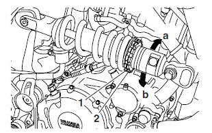
Adjusting the rear shock absorber assembly
WARNING
Securely support the motorcycle so that there is no danger of it falling over.
Spring preload
CAUTION:
Never go beyond the maximum or minimum adjustment positions.
1. Adjust:
- Spring preload
NOTE:
Adjust the spring preload with the special wrench and extension bar included in the owner's tool kit.
a. Loosen the locknut "2".
b. Turn the adjusting ring "1" in direction "a" or "b".
Direction (a) Spring preload is increased (suspension is harder)
Direction (b) Spring preload is decreased (suspension is softer)
 Adjusting positions
Standard: 170 mm (6.69 in)
Adjusting positions
Standard: 170 mm (6.69 in)
Minimum: 174.5 mm (6.87 in)
Maximum: 165.5 mm (6.49 in)
c. Tighten the locknut "2" to specification.
 Locknut
45 Nm (4.5 m*kg, 32.5 ft*lb)
Locknut
45 Nm (4.5 m*kg, 32.5 ft*lb)
Checking the tires
The following procedure applies to both of the tires.
1. Check:
- Tire pressure
Out of specification → Regulate.
WARNING
- The tire pressure should only be checked and regulated when the tire temperature equals the ambient air temperature.
- The tire pressure and the suspension must be adjusted according to the total weight (including cargo, rider, passenger and accessories) and the anticipated riding speed.
- Operation of an overloaded motorcycle
could cause tire damage, an accident or
an injury.
NEVER OVERLOAD THE MOTORCYCL
E.
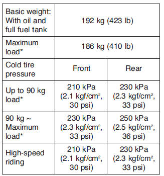
* Total weight of rider, passenger, cargo and accessories
WARNING
It is dangerous to ride with a worn-out tire.
When the tire tread reaches the wear limit, replace the tire immediately.
2. Check:
- Tire surfaces
Damage/wear → Replace the tire.
 Minimum tire tread depth
1.6 mm (0.063 in)
Minimum tire tread depth
1.6 mm (0.063 in)
- Tire tread depth
- Sidewall
- Wear indicator
WARNING
- Do not use a tubeless tire on a wheel designed only for tube tires to avoid tire failure and personal injury from sudden deflation.
- When using tube tires, be sure to install the correct tube.
- Always replace a new tube tire and a new tube as a set.
- To avoid pinching the tube, make sure the wheel rim band and tube are centered in the wheel groove.
- Patching a punctured tube is not recommended.
If it is absolutely necessary to do so, use great care and replace the tube as soon as possible with a good quality replacement.
- Tire
- Wheel
Tube wheel
Tube tire only
Tubeless wheel
Tube or tubeless tire
WARNING
After extensive tests, the tires listed below have been approved by Yamaha Motor Italia S.p.A. for this model. The front and rear tires should always be by the same manufacturer and of the same design. No guarantee concerning handling characteristics can be given if a tire combination other than one approved by Yamaha is used on this motorcycle.
 Front tire
Tire type
Tubeless
Size
120/70-ZR17M/C (58W)
120/70-R17M/C (58H)
Manufacturer/Model
DUNLOP D270F/PIRELLI SCORPION SYNC
 Rear tire
Tire type
Tubeless
Size
160/60-ZR17M/C (69W)
160/60-R17M/C (69H)
Manufacturer/Model
DUNLOP D270/PIRELLI SCORPION SYNC
WARNING
New tires have a relatively low grip on the road surface until they have been slightly worn. Therefore, approximately 100 km should be traveled at normal speed before any high-speed riding is done.
NOTE:
For tires with a direction of rotation mark "1":
- Install the tire with the mark pointing in the direction of wheel rotation
- Align the mark "2" with the valve installation point.
Checking the wheels
The following procedure applies to both of the wheels.
1. Check:
- Wheel
Damage/out-of-round → Replace.
WARNING
Never attempt to make any repairs to the wheel.
NOTE:
After a tire or wheel has been changed or replaced, always balance the wheel.
Checking and lubricating the cables
The following procedure applies to all of the inner and outer cables.
WARNING
Damaged outer cable may cause the cable to corrode and interfere with its movement.
Replace damaged outer cable and inner cables as soon as possible.
1. Check:
- Outer cable.
Damage → Replace.
2. Check:
- Cable operation.
Rough movement → Lubric
 Recommended lubricant
Engine oil or a suitable cable
lubricant
Recommended lubricant
Engine oil or a suitable cable
lubricant
NOTE:
Hold the cable end upright and pour a few drops of lubricant into the cable sheath or use a suitable lubricating device.
Lubricating the levers and brake pedal
Lubricate the pivoting point and metal-to-metal moving parts of the levers and brake pedal.
 Recommended lubricant
Lithium-soap-based grease
Recommended lubricant
Lithium-soap-based grease
Lubricating the sidestand
Lubricate the pivoting point and metal-to-metal moving parts of the sidestand.
 Recommended lubricant
Lithium-soap-based grease
Recommended lubricant
Lithium-soap-based grease
Lubricating the side suspension
The pivoting points of the side suspension must be lubricated at the intervals specified in the periodic maintenance and lubrication chart.
 Recommended lubricant
Swingarm pivots
Bearing grease
Other pivoting points
Lithium-soap-based grease
See also:
 Yamaha MT-03 - Service manual > Engine
Adjusting the valve clearance The following procedure applies to all of the valves.
Yamaha MT-03 - Service manual > Electrical system
Checking and charging the battery Checking the fuses Replacing the headlight bulb NOTE: This model is equipped with a quartz bulb headlight.
 Benelli Imperiale 400
 BMW F900XR
 Honda CB500X
 KTM 390 Adventure
 Triumph Street Triple S
 Yamaha MT-03
 Kawasaki Z400
 Triumph Street Triple S
 Yamaha MT-03