 Kawasaki Z400 - Service manual > Electrical System
Lights and Switches operation Inspection
First Step
Set the gear position in the neutral position.
Turn the gear position in the neutral position.
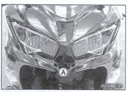
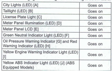
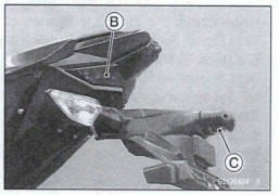
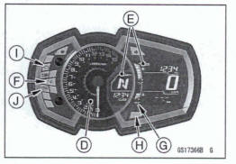
The following lights should go on according to below table.
If the light does not go, inspect or replace the following parts.
Battery (see Charging Condition Inspection in the Electrical System chapter)
Headlight (LED) Assembly (see Headlight (LED) Assembly Removal/ Installation in the Electrical System chapter)
License Plata Light Bulb (see License Plate Light Bulb Replacement in the Electrical System chapter)
Meter Panel LCD (see Meter Unit Inspection in the Electrical System chapter)
Indicator Lights (LED) (see Meter Unit Inspection in the Electrical System chapter)
Meter Panel Illumination (LED) (see Meter Unit Inspection in the Electrical System chapter)
ECU (see ECU Power Supply Inspection in the Fuel System (DFI) chapter)
Main Fuse 30 A, Meter Fuse 10 A and Turn Signal Relay Fuse 10 A (see Fuse Inspection in the Fuel System chapter)
Ignition Switch (see Switch Inspection in the Fuel System chapter)
Oil Pressure Switch (see Inspection in the Electrical system chapter)
Gear Position Sensor (see Gear Position sensor Input Voltage Inspection in the Fuel system (DFI) chapter) Harness (see Wiring Inspection in the Electrical system chapter
- Turn the ignition switch off.
- The all lights should go off
If any light does not go off, replace the ignition switch.
Second Step
Turn the ignition switch on.
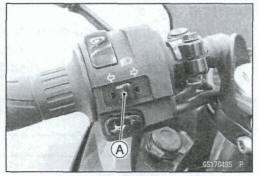
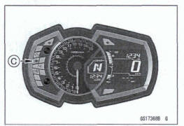
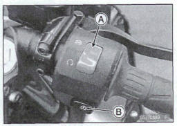
Turn on the turn signal switch [A] (left or right position ).
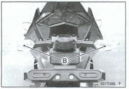
The left or right turn signal lights [B] (front and rear) according to the switch position should blink.
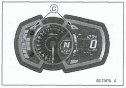
The green turn signal indicator lights (LED) [C] in the meter unit should blink.
If each light does not blink inspect or replace the following parts.
Turn Signal Light Bulb (see Turn Signal Light Bulb Re placement in the Electrical System chapter) Green Turn Signal Indicator Light (LED) (see Meter Unit Inspection In the Electrical System chapter) Turn Signal Relay Fuse 10 A (see Fuse Inspection in the Electrical System chapter) Turn Signal Switch (see Switch Inspection in the Electrical System chapter) 3 Turn Signal Relay (see Turn Signal Relay Inspection in the Electrical System chapter) Harness (see Wiring Inspection in the Electrical System chapter
- Push the turn signal switch.
- The turn signal lights and green turn signal indicator light (LED) should go off.
If the light does not go off, inspect or replace the following parts.
Turn Signal Switch (see Switch Inspection in the Electrical System chapter) Turn Signal Relay (see Turn Signal Relay inspection in the Electrical System chapter
Third Step
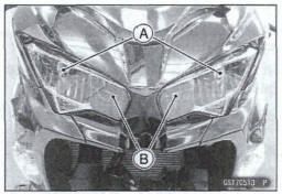
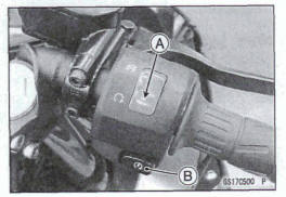
- Set the dimmer switch [A] to low beam position.
- Start the engine.
- The low beam headlights should go on
If the low beam headlights do not go on, inspect or replace the following parts.
Headlight (LED) Assembly (see Headlight (LED) Assembly Removal/Installation in the Electrical System chapter) Headlight Fuse 10 A (see Fuse Inspection in the Electrical System chapter) Dimmer Switch (see Switch Inspection in the Electrical System chapter) Headlight Circuit Relay in Relay Box (see Relay Circuit Inspection in the Electrical System chapter) Harness (see Wiring Inspection in the Electrical System chapter)
- Set the dimmer switch to high beam position.
- The low beam [A] and high beam [B] headlights should go on.
- The blue high beam indicator light (LED) [C] should goes on.
If the high beam headlight and/or blue high beam indicator light (LED) does not go on, inspect or replace the following parts.
Headlight (LED) Assembly (see Headlight (LED) Assembly Removal/Installation in the Electrical System chapter)
Blue High Beam Indicator Light (LED) (see Meter Unit Inspection in the Electrical System chapter)
Dimmer Switch (see Switch Inspection in the Electrical System chapter)
- Turn the engine stop switch to stop position.
- The low beam and high beam headlights should stay going on.
If the headlights and blue high beam indicator light (LED) does go off, inspect or replace the following parts.
Headlight Circuit Relay in Relay Box (see Relay Circuit Inspection in the Electrical System chapter)
- Turn the ignition switch off.
- The headlights and blue high beam indicator light (LED) should go off.
Headlight Aiming Inspection
- Inspect the headlight beam for aiming.
If the headlight beam points to one side rather than straight ahead, adjust the horizontal beam.
Headlight Beam Horizontal Adjustment
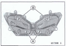
- Turn the horizontal adjuster [A] in both headlights in or out until the beam points straight ahead.
If the headlight beam points too low or high, adjust the vertical beam.
Headlight Beam Vertical Adjustment
- Turn the vertical adjuster [B] in both headlights in or out to adjust the headlight vertically.
NOTE
- On high beam, the brightest points should be slightly below horizontal with the motorcycle on ifs wheels and the rider seated. Adjust the headlight to the proper angle according to local regulations.
- For US model, the proper angle is 0.4 degrees below horizontal. This is 50 mm (2.0 in.) drop at 7.6 m (25 ft) measured from the center of the headlight with the motorcycle on its wheels and the rider seated.
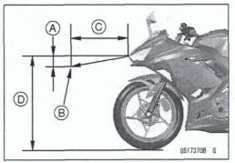
50 mm (2.0 in.) [A] Center of Brightest Spot [B] 7.6 m (25 ft) [C] Height of Headlight Center [D]
Side Stand Switch Operation Inspection
- Raise the rear wheel off the ground with the stand (see Rear Wheel Removal in the Wheels/Tires chapter).
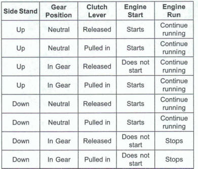
- Inspect the side stand switch [A] operation accordance to below table.
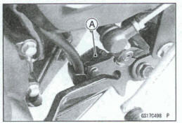
Side Stand Switch Operation
If the side stand switch operation does not work, inspect or replace the following parts
Battery (see Charging Condition Inspection in the Electrical System chapter)
Main Fuse 30 A (see Fuse Inspection in the Electrical System chapter)
Ignition Fuse 10 A (see Fuse Inspection in the Electrical System chapter)
Ignition Switch (see Switch Inspection in the Electrical System chapter)
Side Stand Switch (see Switch Inspection in the Electrical System chapter)
Engine Stop Switch (see Switch Inspection in the Electrical System chapter)
Starter Button (see Switch Inspection in the Electrical System chapter)
Gear Position Sensor (see Gear Position Sensor Input Voltage Inspection in the Fuel System ( DFI ) chapter)
Starter Lockout Switch (see Switch Inspection in the Electrical System chapter)
Starter Relay (see Starter Relay Inspection in the Electrical System chapter)
Relay Box (see Relay Circuit Inspection in the Electrical System chapter)
Starter Circuit Relay (see Relay Circuit Inspection in the Electrical System chapter)
Harness (see Wiring Inspection in the Electrical System chapter)
If the all parts are good condition, replace the ECU (see ECU Removal/Installation in the Fuel System (DFI) chapter).
Engine, Stop Switch Operation Inspection
First Step
- Turn the ignition switch on.
- Set the gear position in the neutral position.
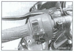
- Turn the engine stop switch to stop position [A].
- Push the starter button [B].
- The engine does not start.
If the engine starts, inspect or replace the engine stop switch (see Switch Inspection in the Electrical System chapter).
Second Step
Turn the ignition switch on.
- Set the gear position in the neutral position.
- Turn the engine stop switch to run position [A].
- Push the starter button [B] and start the engine.
- Turn the engine stop switch to stop position.
- Immediately the engine should be stop
If the engine does not stop, inspect or replace the engine stop switch (see Switch Inspection in the Electrical System chapter ).
If the engine stop switch b good condition, replace the ECU (see ECU R8m0mMnstallation in the Fuel System (DFI) chapter).
Spark Plug Replacement
- Remove the stick coils (see Stick Coil Removal in the Electrical System chapter).
- Remove the spark plugs using the 14 mm (0.55 in.) plug wrench [A] vertically.
- Replace the spark plugs with new ones.
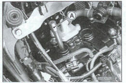
Standard Spark Plug Type: NGK LMAR9G
Insert the spark plug vertically into the spark plug hole with the spark plug installed in the plug wrench [A], and finger-tighten it first.
NOTICE
Of tightening the spark plug with the wrench inclined, the insulator of the spark plug may break.
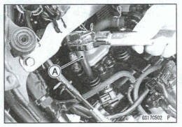
Tighten:
Torque - Spark Plugs: 13 N*m (1.3 kgf*m, 115 In*lb)
- Install the stick coils (see Stick Coil Installation in the Electrical System chapter).
- After installation, be sure the stick mils are installed securely by pulling up hem lightly
See also:
 Kawasaki Z400 - Service manual > Steering
Steering Play Inspection Raise the front wheel off the ground with a suitable stand. With the front wheel pointing straight ahead, alternately tap each end of the handlebar. The front wheel should swing fully left and right from the force of gravity until the fork hits the stop.
Kawasaki Z400 - Service manual > Others
Chassis Parts Lubrication Before lubricating each part, clean off any rusty spots with rust remover and wipe off any grease, dl, dirt, or grime. Lubricate the points listed below with indicated lubricant.
 Benelli Imperiale 400
 BMW F900XR
 Honda CB500X
 KTM 390 Adventure
 Triumph Street Triple S
 Yamaha MT-03
 Kawasaki Z400
 Triumph Street Triple S
 Yamaha MT-03