 Kawasaki Z400 - Service manual > Camshaft, Camshaft Chain
Camshaft Removal
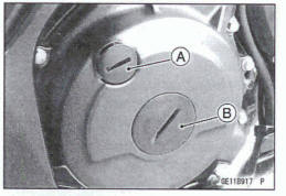
- Remove: Cylinder Head Cover (see Cylinder Head Cover Removal) Timing Inspection Cap [A] Alternator Rotor Bolt Cap [B]
Special Tool - Filler Cap Driver: 57001-1454
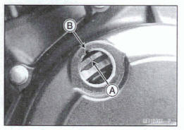
- Position the crankshaft at the specified angle
Using a wrench on the alternator rotor bolt, turn the crankshaft counterclockwise until the line without characters [A] on the alternator rotor is aligned with the groove [B] in the inspection window.
- Remove: Camshaft Chain Tensioner (see Camshaft Chain Tensioner Removal)
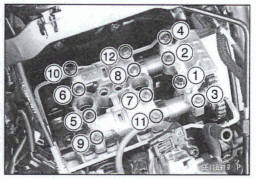
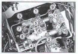
- Loosen the camshaft cap bolts gradually and evenly as shown sequence [1 ~ 12] and remove them.
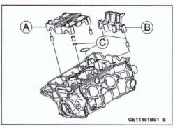
- Remove: Camshaft Cap [A] Upper Chain Guide [B] Dowel Pins O-rings [C] Camshafts
- Stuff a dean doth into the drain tunnel to keep any parts from dropping into the crankcase.
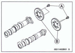
- Remove: Camshaft Sprocket Bolts [A] Camshaft Sprockets [B]
NOTICE
The crankshaft may be turned while the camshafts are removed. Always pull the chain taut while turning the crankshaft. This avoids kinking the chain on the lower (crankshaft) sprocket. A kinked chain could damage both the chain and the sprocket.
Camshaft installation
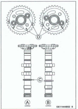
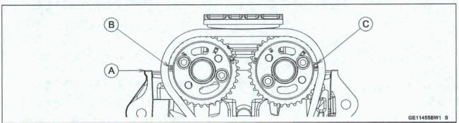
Install the camshaft sprockets as shown.
Exhaust [A] Intake [B]
The exhaust camshaft has the groove [C].
- Apply a non-permanent locking agent to the threads of the camshaft sprocket bolts [D] and tighten them.
Toque -Camshaft Sprocket Bob: 20 N-m (2.0 kgf-m, 15 ft-lb)
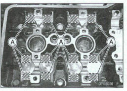
- Apply molybdenum disulfide oil solution to all cam parts and journals.
*If a new camshaft is to be used, apply a thin coat of molybdenum disulfide grease to the cam surfaces.
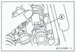
- Pour the engine oil into the position [A] as shown.
- Position the crankshaft at the specified angle (see Camshaft Removal).
NOTICE
The crankshaft may be turned while the camshafts are removed. Always pull the chain taut while turning the crankshaft. This avoids kinking the chain on the lower (crankshaft) sprocket. A kinked chain could damage both the chain and the sprocket.
- Engage the camshaft chain with the camshaft sprockets.
- Pull the tension side (exhaust side) of the chain taut to install the chain on the sprockets.
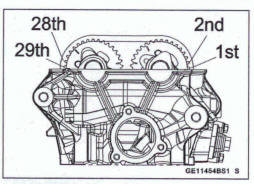
- The shorter timing marks [A] align with the cylinder head
upper surface.
Exhaust [B] Intake [C]
- Count the camshaft chain link pins as shown to verify that the sprocket are positioned correctly.
- Replace the O-rings [A] with new ones.
- Apply grease to the O-rings.
- Install: Dowel Pins [B] Upper Chain Guide Camshaft Cap
- First tighten the all camshaft cap bolts evenly to seat the camshaft in place, then tighten all bolts following the specified tightening sequence [1 ~12].
Torque - Camshaft Cap Bolts: 12 N*m (1 2 kgf*m, 106 in-lb)
Install: Camshaft Chain Tensioner (see Camshaft Chain Tensioner Installation)
Position the crankshaft at #2 piston TDC
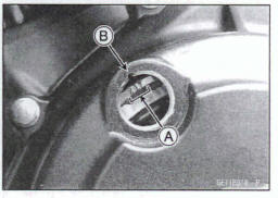
Using a wrench on the alternator rotor bolt, turn the crankshaft counterclockwise until the "2T" mark [A] on the alternator rotor is aligned with the groove [B] in the inspection window.
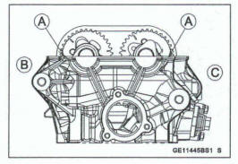
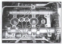
- Check that the timing marks on the camshaft sprockets
are align with the cylinder head upper surface [A].
Intake Side Timing Mark [B] (IN) Exhaust Side Timing Mark [C] (EX)
- Install the removed parts (see appropriate chapters).
Camshaft, Camshaft Cap Wear Inspection
- Remove: Upper Chain Guide (see Camshaft Removal) Camshaft Cap (see Camshaft Removal)
- Cut the strips of plastigauge (press gauge) to journal width. Place a strip on each journal parallel to the camshaft installed in the correct position.
- Tighten the camshaft cap bolts (see Camshaft Installation).
NOTE
Do not turn the camshaft when the plastigauge is between the journal and camshaft cap.
- Remove the camshaft cap again, measure each clearance between the camshaft journal and the camshaft cap using the plastsgauge (press gauge) [A].
Camshaft Journal/Cap Clearance Standard: 0.038 - 0.081 mm (0.0015 - 0.0032 in.) Service Limit: 0.17 mm (0.0067 in.)
*If any clearance exceeds the service limit, measure the diameter of each camshaft journal with a micrometer.
Camshaft Journal Diameter Standard: 23.940 - 23.962 mm (0.94252 - 0.94338 m.) Service Limit: 23.91 mm (0.9413 in.)
*If the camshaft journal diameter is less than the service limit, replace the camshaft with a new one and measure the clearance again.
*If the clearance still remains out of the service limit, replace the cylinder head unit.
Camshaft Runout Inspection
- Remove the camshafts (see Camshaft Removal).
- Set the camshaft In a camshaft alignment jig or on V Mocks.
- Measure the runout with a dial gauge at the specified place as shown
*If the runout exceeds the service limit, replace the camshaft.
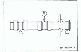
Camshaft Runout Standard: RR 0.02 mm (0.00a8 in.) or less Service Unit: TlR 0.1 mm (0.001 in.)
Cam Wear Inspection
- Remove the camshafts (see Camshaft Removal).
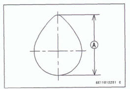
- Measure the height [A] d each cam with a micrometer
*If the cams are worn down past the service it, replace the camshaft.
Cam Height
Standard: Exhaust 32.743 - 32.857 mm (1 9891 - 1.2936 in.)
Intake 33.743 - 33.857 mm (1.3285 - 1.3330 in.) Service Limit: Exhaust 32.64 mm (1285 in.)
Intake 33.64 mm (1.324 in.)
Camshaft Chain Removal
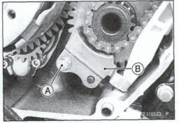
Remove: Clutch Cover (see Clutch Cover Removal in chapter) Camshafts (see Camshaft Removal) Lower Camshaft Chain Guide Bolt [A] Lower Camshaft Chain Guide [B]
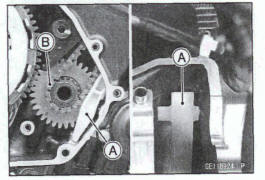
Remove: Front Camshaft Chain Guide [A] Camshaft Chain [B]
Camshaft Chain Installation
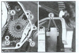
- Engage the camshaft chain [A] to the sprocket on the crankshaft [B].
- Install: Front Camshaft Chain Guide [C]
Fit the chain guide in front of the rib [D] on the crankcase.
Fit the projections [E] of the chain guide to the inside wall of the cylinder head.
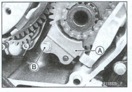
- Install: Lower Camshaft Chain Guide [A]
- Tighten:
Torque - Lower Camshaft Chain Guide Bolt [B]: 9.8 N-m (1.0 kgf*m, 87 in-lb)
See also:
 Kawasaki Z400 - Service manual > Cylinder Head Cover
Cylinder Head Cover Removal Replace the M cover gasket with a new one. Clean off any oil or dirt and apply liquid gasket to the groove [A] of the cylinder head cover.
Kawasaki Z400 - Service manual > Cylinder Head
Cylinder Compression Measurement NOTE Use the battery which is fully charged. Warm up the engine thoroughly. Stop the engine. Remove: Air Cleaner Housing (see Air Cleaner Housing Removal in the Fuel System (DFI) chapter) Stick Coils (see Stick Coil Removal in the Electrical System chapter) Spark Plugs (see Spark Plug Replacement in the Periodic Maintenance chapter) Attach the compression gauge [A] and adapter [B] firmly into the spark plug hole. Using the starter motor, turn the mine over with the throttle fully open until the compression gauge stops rising; the compression is the highest reading obtainable.
 Benelli Imperiale 400
 BMW F900XR
 Honda CB500X
 KTM 390 Adventure
 Triumph Street Triple S
 Yamaha MT-03
 Kawasaki Z400
 Triumph Street Triple S
 Yamaha MT-03