 Triumph Street Triple S - Service manual > Alternator
Removal
1. Remove the rider's seat.
2. Daytona 675 only: Remove the left hand lower fairing.
3. Disconnect the battery, negative (black) lead first.
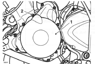
4. Release the bolts securing the left hand engine cover, noting the position of the copper washer under the head of one of the upper bolts. Collect the solenoid/fairing bracket from under the front two bolts.
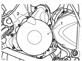
- Left hand engine cover
- Copper washer position
- Solenoid/fairing bracket
5. Withdraw the cover from the crankcase against the pull of the alternator magnet.
Note:
- The stator and crankshaft position sensor are supplied as an assembly and cannot be separated.
6. To remove the stator and crankshaft position sensor from the cover, release the three bolts in the centre of the cover and release the bolt securing the cable bracket. Discard the bolts.
7. Release and discard the fixings securing the crankshaft position sensor to the cover.
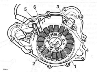
- Stator
- Stator fixings
- Crankshaft position sensor
- Crankshaft position sensor fixings
- Cable bracket
- Cable bracket fixing
8. Withdraw the stator and crankshaft position sensor.
Caution: Do not use tools to tighten service tool T3880375.
Tighten the tool by hand only. Over-tightening of the tool will lead to damage to the alternator rotor.
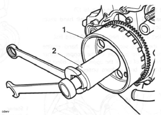
9. To remove the rotor, clean the alternator rotor to remove all traces of oil, and fit tool T3880375 to the rotor as shown below. Retain the tool to prevent the crankshaft from rotating and remove the centre bolt from the crankshaft.
- Rotor
- Tool T3880375
- Centre bolt
10. With the bolt removed, locate the spigot from the larger of the two thrust pads supplied with tool T3880365 to the crankshaft.
- Thrust pad
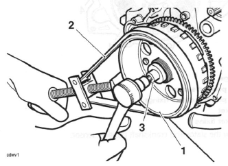
11. Assemble tool T3880365 to the threaded centre section of the rotor.
Note:
- Ensure that the thrust pad does not fall out during assembly of the tool.
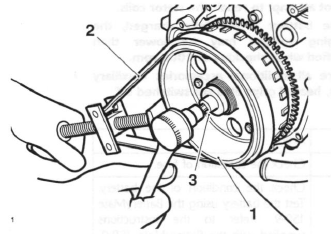
12. Hold the centre of the tool to prevent rotation then tighten the draw-bolt in the centre of the tool to release the taper seating of the rotor from the crankshaft.
- Rotor
- Tool T3880365
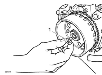
13. Withdraw the rotor and tool as an assembly and then separate the tool from the rotor. Collect the Woodruff Key and the tool thrust pad from the crankshaft.
Assembly
1. Refit the Woodruff key to the crankshaft.
2. Assemble the rotor to the keyway on the crankshaft, ensuring the Woodruff key remains in position.
Caution: Do not use tools to tighten service tool T3880375.
Tighten the tool by hand only. Over-tightening of the tool will lead to damage to the alternator rotor.
3. Refit tool T3880375 to prevent the crankshaft from rotating, ensuring the rotor is free from oil and the tool is not over-tightened.
4. Tighten the rotor retaining bolt to 120 Nm
- Rotor
- Tool T3880375
- Centre bolt
5. Remove tool T3880375.
6. Locate the stator and crankshaft position sensor to the engine cover.
7. Apply silicone sealer to the cable grommet (at the factory, ThreeBond 1215 is used) and align the cable to the exit slot.
8. Fit the cable retainer bracket and tighten a new retainer bolt to 6 Nm.
9. Tighten the new stator bolts to 12 Nm.
10. Tighten the new crankshaft position sensor bolts to 6 Nm.
11. Position a new gasket to the crankcase dowels then refit the left hand engine cover.
12. Ensure the bolt with the copper washer is correctly located. Refit the solenoid/fairing bracket to the front two bolts. Tighten the cover bolts to 9 Nm.
- Left hand engine cover
- Copper washer position
- Solenoid bracket
13. Daytona 675 only: Refit the left hand lower fairing.
14. Reconnect the battery, positive (red) lead first.
15. Refit the seat.
Alternator Rectifier
The rectifier does not contain any serviceable parts and must be replaced if faulty.
Daytona 675 up to VIN 381274, Street Triple and Street Triple R all VINs
The alternator rectifier is located in between the rear suspension unit and the gearbox. To access the rectifier connector, remove the fuel tank.
Daytona 675 from VIN 381275
The alternator rectifier is located under the cockpit's right hand infill panel. To access the rectifier, remove the right hand lower fairing.
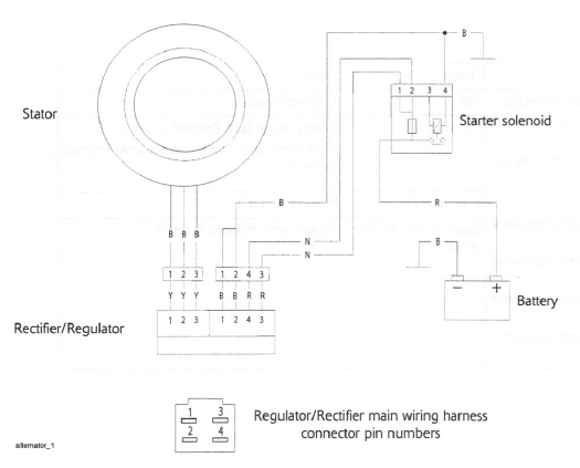
Alternator Stator
The stator is an assembly of 18 coils, arranged into three phases. It is possible to check for continuity, and short circuits through the coils to earth.
Note:
- Only repairs to the stator harness between the connector and the harness entry point into the crankcase are permitted.
- Do not attempt to repair the stator coils.
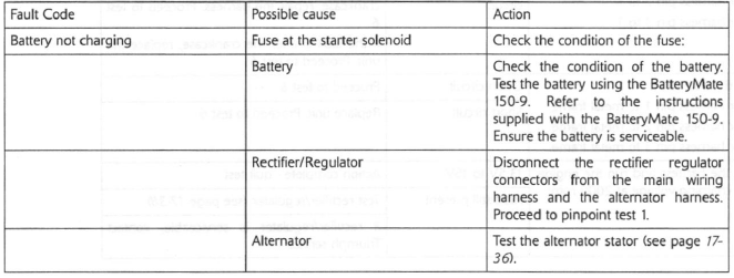
- If the battery is not fully charged, the charging voltage may be lower than specified when checking at 2000 rpm.
- Ensure all additional accessories (auxiliary lights, heated grips etc.) are switched off.
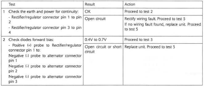
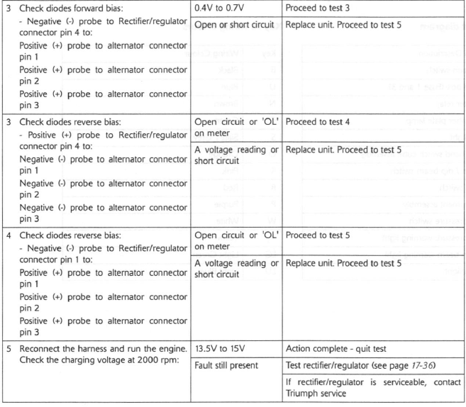
Pinpoint Tests
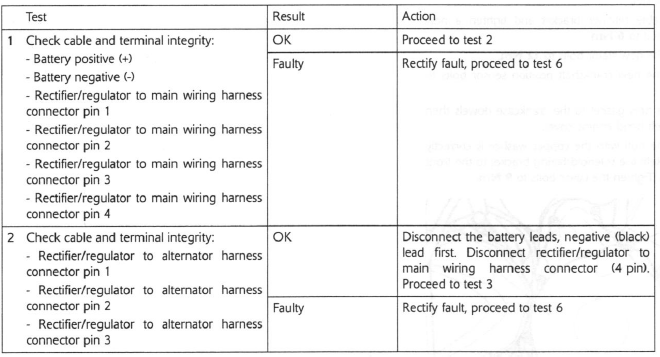
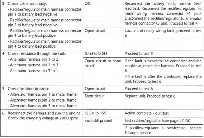
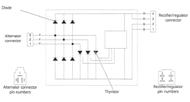
Rectifier/ Regulator
Internally the rectifier/regulator consists of:
- six diodes;
- a voltage controller and three thyristors.
The diodes are arranged with one diode connected between each yellow input wire and each pair of red and black output wires.
The diodes convert the ac voltage to dc voltage.
Each yellow input wire is also connected to a thyristor which is in turn connected to ground. When the dc voltage at the battery reaches the required level, the voltage controller sends a signal to all three thyristors. The thyristors then conduct and effectively short circuit the stator until the dc voltage drops to an acceptable level.
It is possible for any number of these diodes to fail, reducing the power output of the unit. This may not be obvious until maximum power is required by the ignition, lighting and accessories etc.
The diodes can be checked using a multimeter on DIODE setting.
Note:
- This test does not check for voltage regulation.
Pinpoint Tests
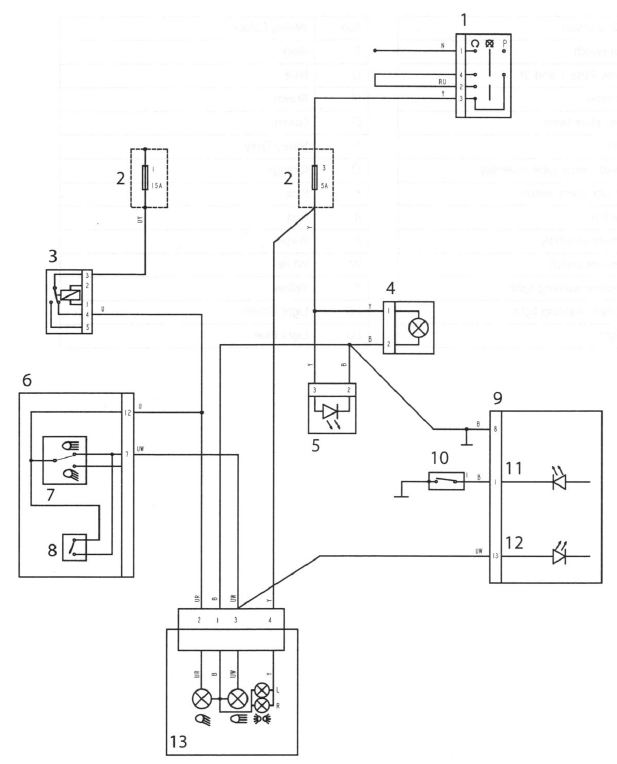
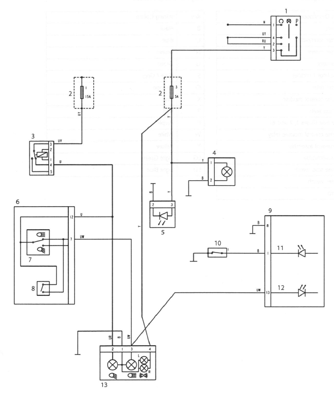
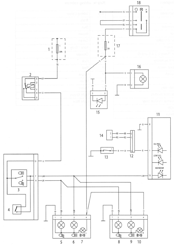
Lighting Circuit - Daytona 675 up to VIN 381274
Key to circuit diagram
- Ignition switch
- Fuse box (Fuse 1 and 3)
- Starter relay
- Number plate lamp
- Tail light
- Left hand switch cube assembly
- Main / dip beam switch
- Pass switch
- Instrument assembly
- Oil pressure switch
- Oil pressure warning light
- Main beam warning light
- Headlight
Key to wiring colours
B Black
U Blue
N Brown
G Green
S Slate / Grey
O Orange
K Pink
R Red
P Purple
W White
Y Yellow
LG Light Green
LU Light Blue
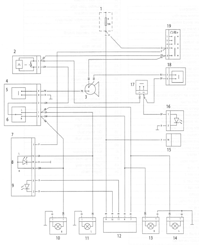
Lighting Circuit - Daytona 675 from VIN 381275
Key to circuit diagram
- Ignition switch
- Fuse box (Fuse 1 and 3)
- Starter relay
- Number plate lamp
- Tail light
- Left hand switch cube assembly
- Main / dip beam switch
- Pass switch
- Instrument assembly
- Oil pressure switch
- Oil pressure warning light
- Main beam warning light
- Headlight
Key to wiring colours
B Black
U Blue
N Brown
G Green
S Slate / Grey
O Orange
K Pink
R Red
P Purple
W White
Y Yellow
LG Light Green
LU Light Blue
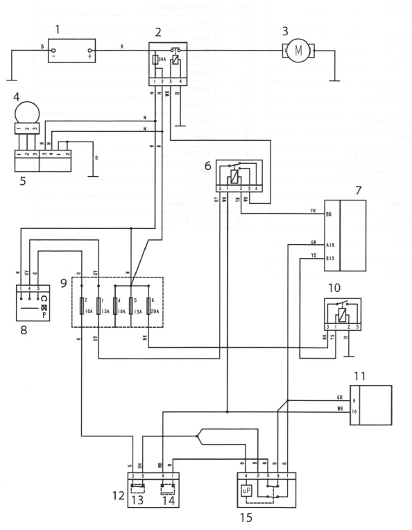
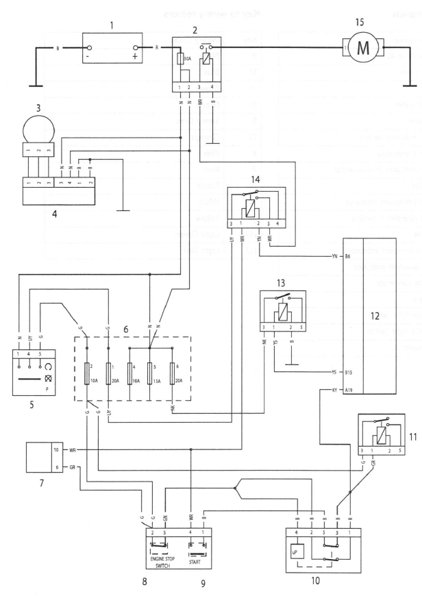
Starting and Charging Circuit - Daytona 675 up to VIN 381274
Key to circuit diagram
- Battery
- Starter solenoid
- Starter motor
- Alternator
- Regulator / rectifier
- Starter relay
- Engine control module
- Ignition switch
- Fuse box (Fuses 1, 2 and 6)
- Engine control module relay
- Instrument assembly
- RH switchcube
- Engine stop switch
- Starter switch
- Alarm
Key to wiring colours
B Black
U Blue
N Brown
G Green
S Slate / Grey
O Orange
K Pink
R Red
P Purple
W White
Y Yellow
LG Light Green
LU Light Blue
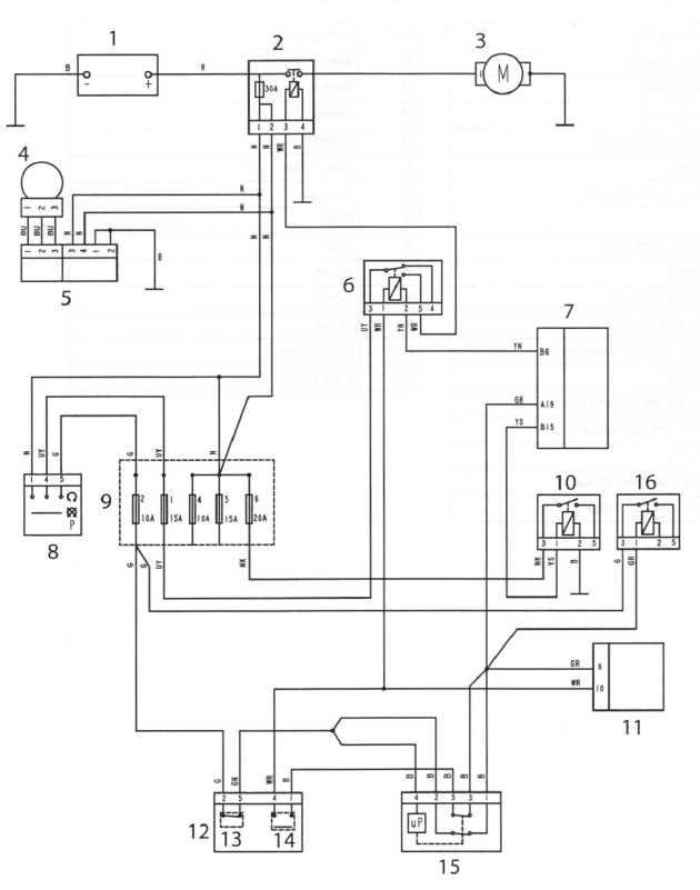
Starting and Charging Circuit - Daytona 675 from VIN 381275
Key to circuit diagram
- Battery
- Starter solenoid
- Starter motor
- Alternator
- Regulator / rectifier
- Starter relay
- Engine control module
- Ignition switch
- Fuse box (Fuses 1, 2 and 6)
- Engine control module relay
- Instrument assembly
- RH switchcube
- Engine stop switch
- Starter switch
- Alarm
- Fuel pump relay
Key to wiring colours
B Black
U Blue
N Brown
G Green
S Slate / Grey
O Orange
K Pink
R Red
P Purple
W White
Y Yellow
LG Light Green
LU Light Blue
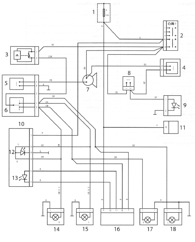
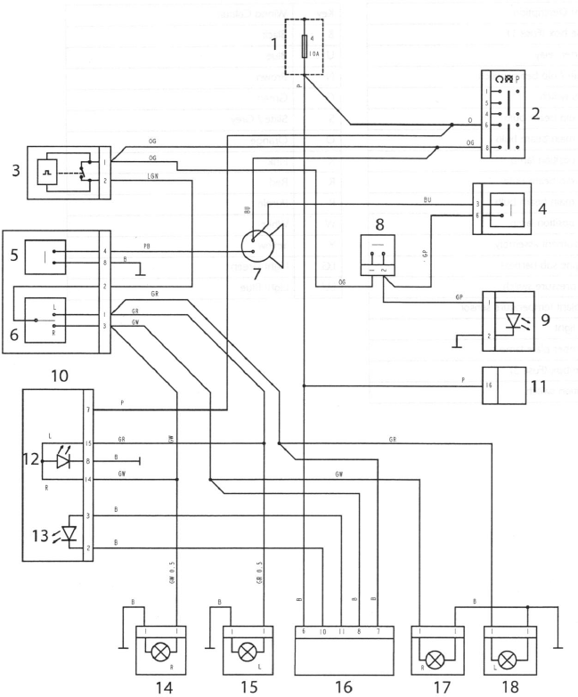
Auxiliary and Accessory Circuit - Daytona 675 up to VIN 381274
Key to circuit diagram
- Fuse box (Fuse 4)
- Ignition switch
- Indicator relay
- Front brake light switch
- Horn switch
- Direction indicator switch
- Horn
- Rear brake light switch
- Brake light
- Instrument assembly
- Diagnostic connector
- Direction indicator (Instruments)
- Alarm LED
- Front right direction Indicator
- Front left direction Indicator
- Alarm unit
- Rear right direction indicator
- Rear left direction indicator
Key to wiring colours
B Black
U Blue
N Brown
G Green
S Slate / Grey
O Orange
K Pink
R Red
P Purple
W White
Y Yellow
LG Light Green
LU Light Blue
Auxiliary and Accessory Circuit - Daytona 675 from VIN 381275
Key to circuit diagram
- Fuse box (Fuse 4)
- Ignition switch
- Indicator relay
- Front brake light switch
- Horn switch
- Direction indicator switch
- Horn
- Rear brake light switch
- Brake light
- Instrument assembly
- Diagnostic connector
- Direction indicator (Instruments)
- Alarm LED
- Front right direction Indicator
- Front left direction Indicator
- Alarm unit
- Rear right direction indicator
- Rear left direction indicator
Key to wiring colours
B Black
U Blue
N Brown
G Green
S Slate / Grey
O Orange
K Pink
R Red
P Purple
W White
Y Yellow
LG Light Green
LU Light Blue
Lighting Circuit - Street Triple and Street Triple R
Key to circuit diagram
- Fuse box (Fuse 1)
- Starter relay
- Main / dip beam switch
- Pass switch
- LH dip beam bulb
- LH main beam bulb
- LH position lamp
- RH dip beam bulb
- RH main beam bulb
- RH position lamp
- Instrument assembly
- Engine sub harness
- Oil pressure switch
- Coolant temperature sensor
- Tail light
- Number plate lamp
- Fuse box (Fuse 3)
- Ignition switch
Key to wiring colours
B Black
U Blue
N Brown
G Green
S Slate / Grey
O Orange
K Pink
R Red
P Purple
W White
Y Yellow
LG Light Green
LU Light Blue
Starting and Charging Circuit - Street Triple and Street Triple R
Key to circuit diagram
- Battery
- Starter solenoid
- Alternator
- Regulator / rectifier
- Ignition switch
- Fuse box (Fuses 1, 2,4,5 and 6)
- Instrument assembly
- Engine stop switch
- Starter switch
- Alarm
- Fuel pump relay
- Engine control module
- Engine control module relay
- Starter relay
- Starter motor
Key to wiring colours
B Black
U Blue
N Brown
G Green
S Slate / Grey
O Orange
K Pink
R Red
P Purple
W White
Y Yellow
LG Light Green
LU Light Blue
Auxiliary and Accessory Circuit - Street Triple and Street Triple R
Key to circuit diagram
- Fuse box (Fuse 4)
- Indicator relay
- Horn
- LH switch cube
- Horn switch
- Direction indicator switch
- Instrument assembly
- Direction indicator (Instruments)
- Alarm LED
- Front right direction Indicator
- Front left direction Indicator
- Alarm unit
- Rear right direction indicator
- Rear left direction indicator
- Diagnostic connector
- Brake light
- Rear brake light switch
- Front brake light switch
- Ignition switch
Key to wiring colours
B Black
U Blue
N Brown
G Green
S Slate / Grey
O Orange
K Pink
R Red
P Purple
W White
Y Yellow
LG Light Green
LU Light Blue
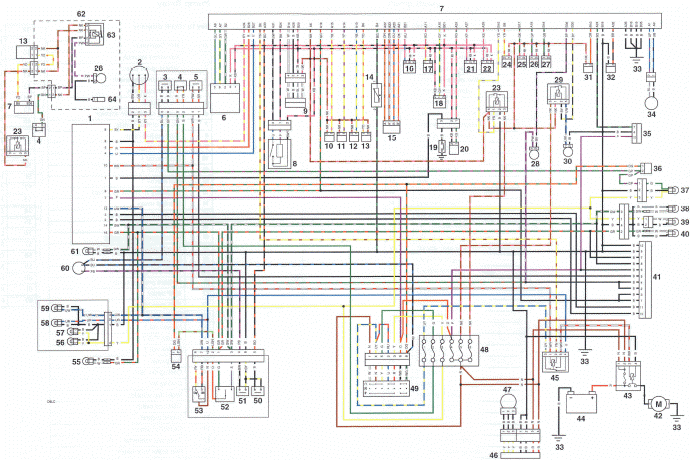
Complete System - Daytona 675 up to VIN 300525 with/without Fuel Pump Relay Modification
Key to circuit diagram
- Instrument assembly
- Vehicle speed sensor
- Front brake lever switch
- Engine stop switch
- Starter button
- Exhaust control valve actuator
- Engine control module
- Gear position sensor
- Lambda sensor
- Fuel injector 1
- Fuel injector 2
- Fuel injector 3
- Secondary air injection solenoid
- Low fuel sensor
- Idle speed control actuator
- Fall detection switch
- Inlet air temperature sensor
- Throttle potentiometer
- Oil pressure switch
- Coolant temperature sensor
- Ambient pressure sensor
- MAP sensor
- EMS main relay
- Purge valve
- Ignition coil 1
- Ignition Coil 2
- Ignition coil 3
- Fuel pump
- Cooling fan relay
- Cooling fan
- Intake flap actuator
- Sidestand switch
- Engine ground
- Crankshaft sensor
- Diagnostic connector
- Rear brake lever switch
- Rear light
- RH rear indicator
- Number plate light
- LH rear indicator
- Alarm connector (accessory)
- Starter motor
- Starter solenoid (fused)
- Battery
- Starter relay
- Rectifier / regulator
- Alternator
- Fuse box
- Ignition switch
- Clutch lever switch
- Horn button
- Direction indicator switch
- Headlamp dip switch
- Direction indicator unit
- LH front indicator
- LH position light
- RH position light
- Dip beam bulb
- Main beam bulb
- Horn
- RH front indicator
- Fuel pump relay modification
- Fuel pump relay
- Engine earth
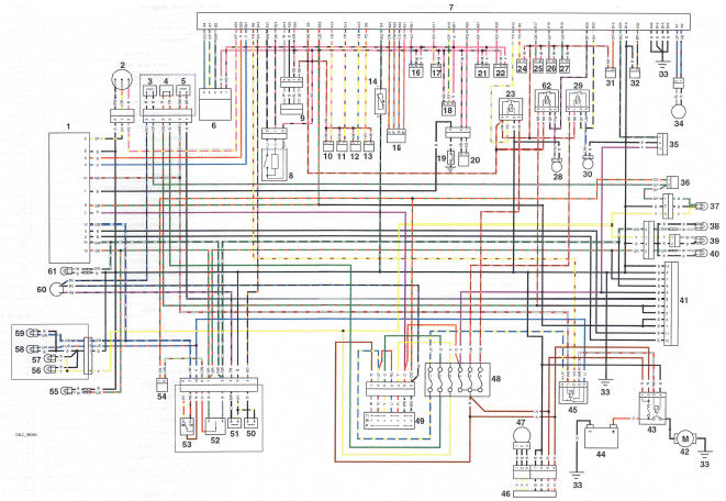
Complete System - Daytona 675 from VIN 300526 to VIN 323544 with Fuel Pump Relay
Key to circuit diagram
- Instrument assembly
- Vehicle speed sensor
- Front brake lever switch
- Engine stop switch
- Starter button
- Exhaust control valve actuator
- Engine control module
- Gear position sensor
- Lambda sensor
- Fuel injector 1
- Fuel injector 2
- Fuel injector 3
- Secondary air injection solenoid
- Low fuel sensor
- Idle speed control actuator
- Fall detection switch
- Inlet air temperature sensor
- Throttle potentiometer
- Oil pressure switch
- Coolant temperature sensor
- Ambient pressure sensor
- MAP sensor
- EMS main relay
- Purge valve
- Ignition coil 1
- Ignition Coil 2
- Ignition coil 3
- Fuel pump
- Cooling fan relay
- Cooling fan
- Intake flap actuator
- Sidestand switch
- Engine ground
- Crankshaft sensor
- Diagnostic connector
- Rear brake lever switch
- Rear light
- RH rear indicator
- Number plate light
- LH rear indicator
- Alarm connector (accessory)
- Starter motor
- Starter solenoid (fused)
- Battery
- Starter relay
- Rectifier / regulator
- Alternator
- Fuse box
- Ignition switch
- Clutch lever switch
- Horn button
- Direction indicator switch
- Headlamp dip switch
- Direction indicator unit
- LH front indicator
- LH position light
- RH position light
- Dip beam bulb
- Main beam bulb
- Horn
- RH front indicator
- Fuel pump relay
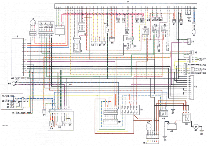
Complete System - Daytona 675 - from VIN 323545 to VIN381274
Key to circuit diagram
- Instrument assembly
- Vehicle speed sensor
- Front brake lever switch
- Engine stop switch
- Starter button
- Exhaust control valve actuator
- Engine control module
- Gear position sensor
- Lambda sensor
- Fuel injector 1
- Fuel injector 2
- Fuel injector 3
- Secondary air injection solenoid
- Low fuel sensor
- Idle speed control actuator
- Fall detection switch
- Inlet air temperature sensor
- Throttle potentiometer
- Oil pressure switch
- Coolant temperature sensor
- Ambient pressure sensor
- MAP sensor
- EMS main relay
- Purge valve
- Ignition coil 1
- Ignition Coil 2
- Ignition coil 3
- Fuel pump
- Cooling fan relay
- Cooling fan
- Intake flap actuator
- Sidestand switch
- Engine ground
- Crankshaft sensor
- Diagnostic connector
- Rear brake lever switch
- Rear light
- RH rear indicator
- Number plate light
- LH rear indicator
- Alarm connector (accessory)
- Starter motor
- Starter solenoid (fused)
- Battery
- Starter relay
- Rectifier / regulator
- Alternator
- Fuse box
- Ignition switch
- Clutch lever switch
- Horn button
- Direction indicator switch
- Headlamp dip switch
- Direction indicator unit
- LH front indicator
- LH position light
- RH position light
- Dip beam bulb
- Main beam bulb
- Horn
- RH front indicator
- Fuel pump relay
Key to wiring colours
B Black
U Blue
N Brown
G Green
S Slate / Grey
O Orange
K Pink
R Red
P Purple
W White
Y Yellow
LG Light Green
LU Light Blue
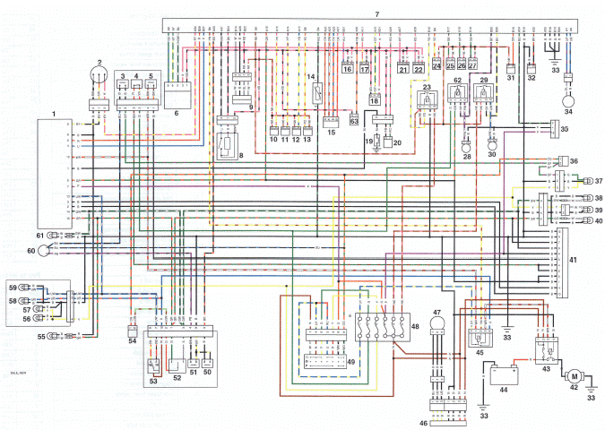
Complete System - Daytona 675 - from VIN 381275
Key to circuit diagram
- Instrument assembly
- Vehicle speed sensor
- Front brake lever switch
- Engine stop switch
- Starter button
- Exhaust control valve actuator
- Engine control module
- Gear position sensor
- Lambda sensor
- Fuel injector 1
- Fuel injector 2
- Fuel injector 3
- Secondary air injection solenoid
- Low fuel sensor
- Idle speed control actuator
- Fall detection switch
- Inlet air temperature sensor
- Throttle potentiometer
- Oil pressure switch
- Coolant temperature sensor
- Ambient pressure sensor
- MAP sensor
- EMS main relay
- Purge valve
- Ignition coil 1
- Ignition Coil 2
- Ignition coil 3
- Fuel pump
- Cooling fan relay
- Cooling fan
- Intake flap actuator
- Sidestand switch
- Engine ground
- Crankshaft sensor
- Diagnostic connector
- Rear brake lever switch
- Rear light
- RH rear indicator
- Number plate light
- LH rear indicator
- Alarm connector (accessory)
- Starter motor
- Starter solenoid (fused)
- Battery
- Starter relay
- Rectifier / regulator
- Alternator
- Fuse box
- Ignition switch
- Clutch lever switch
- Horn button
- Direction indicator switch
- Headlamp dip switch
- Direction indicator unit
- LH front indicator
- LH position light
- RH position light
- Dip beam bulb
- Main beam bulb
- Horn
- RH front indicator
- Fuel pump relay
- Accessory quickshifter
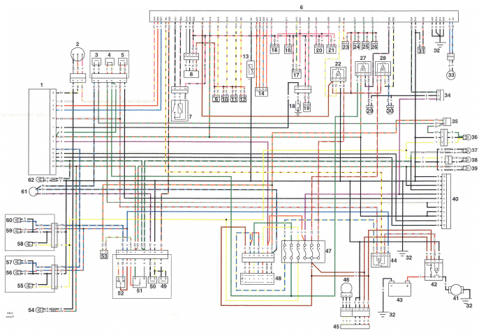
Complete System - Street Triple and Street Triple R
Key to circuit diagram
- Instrument assembly
- Vehicle speed sensor
- Front brake lever switch
- Engine stop switch
- Starter button
- Engine control module
- Gear position sensor
- Lambda sensor
- Fuel injector 1
- Fuel injector 2
- Fuel injector 3
- Secondary air injection solenoid
- Low fuel sensor
- Idle speed control actuator
- Fall detection switch
- Inlet air temperature sensor
- Throttle potentiometer
- Oil pressure switch
- Coolant temperature sensor
- Ambient pressure sensor
- MAP sensor
- EMS main relay
- Purge valve
- Ignition coil 1
- Ignition Coil 2
- Ignition coil 3
- Fuel pump relay
- Fuel pump
- Cooling fan relay
- Cooling fan
- Sidestand switch
- Engine ground
- Crankshaft sensor
- Diagnostic connector
- Rear brake lever switch
- Rear light
- RH rear indicator
- Number plate light
- LH rear indicator
- Alarm connector (accessory)
- Starter motor
- Starter solenoid (fused)
- Battery
- Starter relay
- Rectifier / regulator
- Alternator
- Fuse box
- Ignition switch
- Clutch lever switch
- Horn button
- Direction indicator switch
- Headlamp dip switch
- Direction indicator unit
- LH front indicator
- LH position light
- LH dip beam bulb
- LH main beam bulb
- RH position light
- RH Dip beam bulb
- RH main beam bulb
- Horn
- RH front indicator
Key to wiring colours
B Black
U Blue
N Brown
G Green
S Slate / Grey
O Orange
K Pink
R Red
P Purple
W White
Y Yellow
LG Light Green
LU Light Blue
See also:
 Triumph Street Triple S - Service manual > Direction Indicators
Bulb Replacement Daytona 675 up to VIN 381274 Direction indicator lens Screw
 Benelli Imperiale 400
 BMW F900XR
 Honda CB500X
 KTM 390 Adventure
 Triumph Street Triple S
 Yamaha MT-03
 Kawasaki Z400
 Triumph Street Triple S
 Yamaha MT-03